D4C-1650 Omron, D4C-1650 Datasheet - Page 21
D4C-1650
Manufacturer Part Number
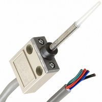
D4C-1650
Description
SMALL LIMIT SWITCH/UL
Manufacturer
Omron
Series
D4Cr
Type
Limitr
Specifications of D4C-1650
Rohs Compliant
YES
Circuit
SPDT
Switch Function
On-Mom
Contact Rating @ Voltage
5A @ 250VAC
Actuator Type
Spring Rod
Mounting Type
Chassis Mount
Termination Style
Cable Leads
Operating Force
147gf
Contact Form
SPDT
Contact Rating
5 Amps at 250 VoltsAC, 4 Amps at 30 VoltsDC
Actuator
Rod
Ingress Protection
IP67
Actuator Style
Rod
Operating Force Max
1.47N
Contact Voltage Ac Max
250V
Contact Voltage Dc Max
30V
Contact Current Ac Max
5A
Contact Current Dc Max
4A
Switch Terminals
Cable
Lead Free Status / RoHS Status
Lead free / RoHS Compliant
Lead Free Status / RoHS Status
Lead free / RoHS Compliant
Other names
D4C-1650
D4C1650
Q3054579
Z2723
D4C1650
Q3054579
Z2723


Mounting
A maximum of 6 Switches may be group-mounted. In this case, pay
attention to the mounting direction so that the convex part of the
group-mounting guide on one Switch fits into the concave part of the
guide on the other Switch as shown in the figure below. For group
mounting, the mounting panel must have a thickness (t) of 6 mm min.
If the mounting panel is warped or has protruding parts, a malfunc-
tion may result. Make sure that the mounting panel is not warped and
has even surfaces.
Mounting Holes
Use a Switch with a rubber cap when using the plunger type in an
environment where malfunction is possible due to environmental
conditions such as dust or cutting chips which may not allow reset-
ting.
180
Cat. No. C032-E1-10
Group-mounting guide
(Front: convex
Rear: concave)
Group Mounting
Group-mounting guide
(Front: convex
Rear: concave)
Enclosed Switch
ALL DIMENSIONS SHOWN ARE IN MILLIMETERS.
To convert millimeters into inches, multiply by 0.03937. To convert grams into ounces, multiply by 0.03527.
Two, 5.2-dia. or M5 screw holes
16 mm
In the interest of product improvement, specifications are subject to change without notice.
D4C
Mounting panel
t
Do not expose the Switch to water exceeding 70 C or use it in steam.
When the D4C is used in a circuit of a device to be exported to
Europe, classified as Overvoltage Class III as specified in IEC664,
provide a contact protection circuit.
Tighten each screw to a torque according to the following table.
Note: By removing the two screws from the head, the head direction
Micro-load Models (D4C-4, -5, -6)
Switching Range
Micro-load models can be used for switching in the range shown
below.
1
2
3
No.
can be rotated 180 . After changing the head direction, re-tight-
en to the torque specified above. Be careful not to allow any for-
eign substance to enter the Switch.
M5 Allen-head bolt
M3.5 head mounting screw
M5 Allen-head bolt
30
24
12
5
0
0.1
Switching
not possible
in this range
5 mW
0.16 mA
Type
1 mA
1
Switching
range for
micro-load
models
10
800 mW
26 mA
4.90 to 5.88 N·m
0.78 to 0.88 N·m
4.90 to 5.88 N·m
100 mA 160 mA
Current (mA)
100
Switching
range for
standard-
load
models
Torque
1,000
Related parts for D4C-1650
Image
Part Number
Description
Manufacturer
Datasheet
Request
R

Part Number:
Description:
SWITCH LIMIT ROLL PLNGR SPDT 5A
Manufacturer:
Omron
Datasheet:

Part Number:
Description:
SWITCH LIMIT PLUNGER SPDT 5A
Manufacturer:
Omron
Datasheet:

Part Number:
Description:
SWITCH LIMIT ROLLER SPDT 5A
Manufacturer:
Omron
Datasheet:

Part Number:
Description:
Switch, Limit, SLIM Enclosed, Roller LEVER, 3M CABLE
Manufacturer:
Omron Automation
Datasheet:
Part Number:
Description:
Switch, PREWIRED, Limit, Sealed, COMPACT, Roller PLUNGER, 1.2KG OPERATING FORCE
Manufacturer:
Omron Automation
Datasheet:
Part Number:
Description:
Switch, PREWIRED, Limit, Sealed, COMPACT, PIN PLUNGER Actuator, 1.2KG OPER. FORCE
Manufacturer:
Omron Automation
Datasheet:
Part Number:
Description:
Switch, Limit, SPDT, Sealed CROSS Roller PLUNGER, 5A, 125VAC, PLUG-IN
Manufacturer:
Omron Automation
Datasheet:

Part Number:
Description:
OPERATING HEAD FOR D4C-1602
Manufacturer:
Omron
Datasheet:
Part Number:
Description:
ACTUATING HEAD D4C-1620
Manufacturer:
Omron
Datasheet:
Part Number:
Description:
0.1A 125 VAC, SEALED RLR PLGR
Manufacturer:
Omron
Datasheet:
Part Number:
Description:
LSW,PIN PLUNGER, 5M VCTF CBL
Manufacturer:
Omron
Datasheet:
Part Number:
Description:
SMALL LIMIT SWITCH/UL
Manufacturer:
Omron
Datasheet:
Part Number:
Description:
LS LOW TEM -40+40C
Manufacturer:
Omron
Datasheet:
Part Number:
Description:
LS P/N PNG 5M CBL
Manufacturer:
Omron
Datasheet: