E2E2-X5MB1M1 Omron, E2E2-X5MB1M1 Datasheet - Page 15
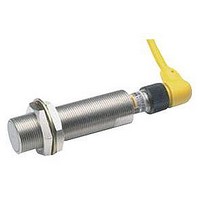
E2E2-X5MB1M1
Manufacturer Part Number
E2E2-X5MB1M1
Description
E2E2-X5MB1 W/ M12 CONNECTOR
Manufacturer
Omron
Datasheet
1.E2E2-X5MB1-M1.pdf
(48 pages)
Specifications of E2E2-X5MB1M1
Rohs Compliant
YES
Sensor Input
Inductive
Sensing Range
5mm
Supply Voltage Range Dc
12V To 24V


E2E2-X@Y@ AC 2-wire Models
Note 1. When supplying 24 VAC to any of the above models, make sure that the operating ambient temperature range is –25 ° C to 85 ° C.
Sensing distance
Set distance
Differential travel
Sensing object
Standard sensing object Iron, 12 x 12 x
Response speed
Power supply voltage
(operating voltage
range) (See note 1.)
Leakage current
Control
output
Indicator
Operation mode (with
sensing object
approaching)
Ambient temperature
Ambient humidity
Temperature influence
Voltage influence
Insulation resistance
Dielectric strength
Vibration resistance
Shock resistance
Degree of protection
Connection method
Weight (packed state)
Material
Accessories
2. When using an M18-or M30-sized E2E2 within an ambient temperature of 70 ° C to 85 ° C, make sure that the E2E2 has a control output of
3. This OMRON in-house standard confirms resistance to cutting and other oils. It is equivalent to the former JEM standard.
5 to 200 mA maximum.
Item
Load
current
(See note
2.)
Residual
voltage
Case
Sensing
surface
Clamping
nuts
Toothed
washer
Type
Size
2 mm ± 10%
0 to 1.6 mm
10% max. of sensing distance
Ferrous metal (The sensing distance decreases with non-ferrous metal, refer to Engineering Data.)
1 mm
25 Hz
24 to 240 VAC, 50/60 Hz (20 to 264 VAC)
1.7 mA max.
5 to 200 mA
Refer to Engineering Data.
Operation indicator (red LED)
Y1 Models:
Y2 Models:
For details, refer to Timing Charts.
Operating/Storage: –40 ° C to 85 ° C (with no icing or condensation) (See notes 1 and 2.)
Operating/Storage: 35% to 95% (with no condensation)
± 15% max. of sensing distance at 23 ° C in the temperature range of –40 ° C to 85 ° C
± 10% max. of sensing distance at 23 ° C in the temperature range of –25 ° C to 70 ° C
± 1% max. of sensing distance in the rated voltage range ± 15%
50 M Ω min. (at 500 VDC) between current-carrying parts and case
4,000 VAC at 50/60 Hz for 1 min between current-carrying parts and case
10 to 55 Hz, 1.5-mm double amplitude for 2 hours each in X, Y, and Z directions
1,000 m/s
IEC 60529 IP67
In-house standard for oil resistance (former JEM standard equivalent to IP67g)
Pre-wired models (standard length: 2 m)
Approx. 65 g
Brass
PBT (polybutylene terephthalate)
Brass-nickel plated
Iron-zinc plated
Instruction manual
E2E2-X2Y@
Shielded
2
, 10 times each in X, Y, and Z directions
NO
NC
M12
5 mm ± 10%
0 to 4.0 mm
Iron, 15 x 15 x
1 mm
E2E2-X5MY@
Unshielded
5 mm ± 10%
0 to 4.0 mm
Iron, 18 x 18 x
1 mm
5 to 300 mA
Approx. 150 g
E2E2-X5Y@
Shielded
E2E/E2E2
M18
10 mm ± 10%
0 to 8.0 mm
Iron, 30 x 30 x
1 mm
E2E2-X10MY@
Unshielded
Cylindrical Proximity Sensor
10 mm ± 10%
0 to 8.0 mm
Iron, 30 x 30 x
1 mm
Approx. 210 g
(See note 3.)
E2E2-X10Y@
Shielded
M30
18 mm ± 10%
0 to 14.0 mm
Iron, 54 x 54 x
1 mm
E2E2-X18MY@
Unshielded
15
Related parts for E2E2-X5MB1M1
Image
Part Number
Description
Manufacturer
Datasheet
Request
R

Part Number:
Description:
Proximity Sensors Long 5 mm Sens NPN M12 Conn
Manufacturer:
Omron
Datasheet:
Part Number:
Description:
PROX LONG M30, 10mm NPN-NC 2M
Manufacturer:
Omron
Datasheet:
Part Number:
Description:
PROX LONG M18, 10mm PNP-NO 2M
Manufacturer:
Omron
Datasheet:
Part Number:
Description:
PROX LONG M18,10mm NPN-NO 2M
Manufacturer:
Omron
Datasheet:

Part Number:
Description:
PROX LONG M30,10mm AC2W-NO(COO
Manufacturer:
Omron
Datasheet:
Part Number:
Description:
PROX LONG M12,2mm NPN-NC 2M
Manufacturer:
Omron
Datasheet:
Part Number:
Description:
PROX LONG M12,2mm AC2W-NC 2M
Manufacturer:
Omron
Datasheet:
Part Number:
Description:
PROX LONG M18,5mm NPN-NC 2M
Manufacturer:
Omron
Datasheet: