XPSAF5130 TELEMECANIQUE, XPSAF5130 Datasheet
XPSAF5130
Specifications of XPSAF5130


Related parts for XPSAF5130


XPSAF5130 Summary of contents
Page 1
Machine safety 1 2 Preventa Ingenious 3 safety functions of your automation system export your machines to any location in the world, you expect solutions that are both Select approved Preventa maintain productivity, you need solutions ...
Page 2
... Safety switches p Safety limit switches and mats p Safety light curtains Operator dialogue ........................................9/22 to 9/26 p Emergency stops p Foot switches p Two-hand control and enabling switches p Products for explosive atmospheres (see chapter 10 “Explosive Atmospheres”) Motor control ....................................................9/27 to 9/29 p Switch disconnectors p TeSys motor starters 1 2 ...
Page 3
Functional Safety and Safety Integrity Level (SIL) Process Process 1 Functional safety of electrical / electronic / Functional safety of electrical / electronic / programmable electronic safety-related systems programmable electronic safety-related systems 2 EN IEC 61511 EN IEC 61511 3 ...
Page 4
Machinery: Risk estimation and SIL assignment of EN IEC 62061 Given as an example in an informative Annex Risk related Risk related Severity of Severity the to the the possible the possible identified identified harm harm ...
Page 5
Safety of Machinery: b The parameter for the failure rate in EN ISO 13849-1 is the Mean Time To Failure (MTTF). This time value indicates the number of years in which the fi rst 1 failure probably occurs. p MTTF ...
Page 6
SafetySuite V2 SafetySuite V2 for machine safety available in 4 complete versions and 3 versions updated, adapted to your particular needs: b Protect Area Design Safety light curtains and sensing mats confi guration software. b ASI SWIN AS-Interface ...
Page 7
Preventa Automation For all XPSMF PLCs p Maximum category of the solution .................................. Category 4 (EN 954-1) p Max performance level for the solution .......................... (EN ISO 13849-1) p Max safety integrity level for the solution ........................ ...
Page 8
For all XPSMF PLCs p Maximum category of the solution .................................. Category 4 (EN 954-1) p Max performance level for the solution .......................... PL e (EN ISO 13849-1) p Max safety integrity level for the solution ........................ SIL 3 (EN ...
Page 9
... XPSMCTS16 and XPSMCTS32 or set of spring clip terminal plug-in connectors XPSMCTC16 and XPSMCTC32 to be ordered separately. (3) For fi xed connector version, delete the letter P from the end of the reference (example: XPSMP11123P becomes XPSMP11123). 9/8 Safety controllers for monitoring emergency stops and limit switches Category 4 Safety solid-state Additional – ...
Page 10
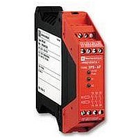
... Category 4 3N/O 3N/O 3N/O 1 solid-state – 1N solid-state 2N solid-state 3 solid-state 22 – – – XPSAC5121P XPSAF5130P XPSAK311144P XPSAR311144P – – – – coded magnetic switches enabling switch Category 4 2 coded magnetic 6 coded magnetic switches maximum switches maximum 2N/O 2N/O 2 solid-state 2 solid-state ...
Page 11
Preventa Automation For all XPSMC controllers p Max performance level for the solution (EN ISO 13849-1) ................... Max safety integrity level for the solution (EN IEC 62061) ....................SIL 3 1 Maximum category of the solution (EN 954-1) Number ...
Page 12
Maximum category of the solution (EN 954-1) Number of circuits Safety Additional Display (number of LEDs) Width of housing Optimum solutions: safety modules (for monitoring 1 safety function) Supply voltage 24 VDC 24 VAC/DC (1) For version with non removable ...
Page 13
Preventa AS-Interface safety at work For all ASISAFEMON monitors p Max performance level for the solution ......................... (EN ISO 13849-1) p Max safety integrity level for the solution ........................ SIL 3 (EN IEC 62061) Maximum category of ...
Page 14
Interface type Degree of protection Dimensions (mm) AS-Interface profi le Consumption from AS-Interface Infrared addressing Connection on AS-Interface Reference with N/C + N/C contact (head not included) Reference of head (Ø40 latching mushroom head, turn ...
Page 15
... With entry for n° 13 (Pg 13.5) cable gland, replace the last digit in the reference by 1 (example: XCSA502 becomes XCSA501). 8 For safety switches XCSMP References 9 References (1) For mm, reference = XCSZ15. 10 For safety switches XCSA/B/C/E References 9/14 Safety switches and actuators 3-pole contact Slow break (N/C + N/O + N/O) ...
Page 16
... N/C + N/O + N/O, 2 N/O staggered slow break XCSTL582 Complete switch N/C + N/C + N/O, N/O staggered slow break (1) With entry for n° 11 (Pg 11) cable gland, replace the last digit in the reference by 1 (example: XCSTL582 becomes XCSTL581). Safety switches with rotary lever or spindle 20/22 20/22 Stainless steel, elbowed (fl ...
Page 17
... NO O1 4/ – 2 3/BU Type of system With integrated safety module 2 Switches for actuation Degree of protection Type of contact Rated operational characteristics Dimensions Operating zone 3 References Connection 4 5 (1) (1) Contact (N/C + N/O, N/C 6 staggered) Contact (N/O + N/O, 1N/O staggered) Plastic switches 7 Switches for actuation ...
Page 18
... Degree of protection Dimensions (body + head (mm) Complete switch N/C + N/C + N/O snap action N/C + N/C + N/O slow break (2) For Pg 13.5 and 1/2" NPT cable entries, refer to www.schneider-electric.com. Limit switches Safety limit switches Metal Roller plunger end plunger Type XCSM, metal pre-cabled (1) 0.5 m/s ...
Page 19
Preventa Detection 1 (1) For simplifi cation of installation, see the “Protect Area design” software confi guration tool. Reference: SISCD104200 Maximum category usage (EN 954-1) 2 Degree of protection Response time (s) Sensitivity Maximum load Connection (2) Dimensions W x ...
Page 20
Light curtain functions • Auto/Manual, • Monitoring of external switching devices (EDM: External Devices Monitoring), • LED display of operating modes Type Slim range Nominal sensing distance (Sn) Detection capacity Number of safety circuits Response time (depending on model) Connection ...
Page 21
Preventa Detection Light curtain functions • Auto/Manual/Manual 1 cycle st • Monitoring of external switching devices (EDM: External Devices Monitoring), • Test input (MTS: Monitoring Test Signal), • Blanking (ECS/B), 1 • Floating Blanking (FB), • Blanking + Floating Blanking, ...
Page 22
Light curtain functions • Auto/Manual/Manual 1 cycle st • Monitoring of external switching devices (EDM: External Devices Monitoring), • Test input (MTS: Monitoring Test Signal), • Alignment aid by LED display of each light beam broken, • LED display of ...
Page 23
Preventa Operator dialogue N/C + N/O contact 1 N/C + N/O + N/C contact Pushbuttons 2 Mechanical life (millions of operating cycles) Shock / vibration resistance Degree of protection Rated operational characteristics Dimensions Ø x Depth Contact N/C + N/O ...
Page 24
N/C + N/O contact slow break N/C + N/C contact slow break For operating cable length ≤ Mechanical life (millions of operating cycles) Shock / vibration resistance Degree of protection Rated operational characteristics Dimensions ...
Page 25
... N/C + N/O XPEM711 XPER711 2 N/C + N/O XPEM529 XPER529 Double pedal switches Foot switches without protective cover 2 cable entries for n° 16 (Pg 16) cable gland (1) With (positive operating action reqd.) Blue Orange 100 joules AC 15, A 300 / DC 13, Q 300 (conforming to EN IEC 60947-5-1) ...
Page 26
... N/C + N/O XPEG810 XPEB110 2 N/C + N/O – XPEB111 2 N/C + N/O XPEG911 XPEB211 Foot switches with protective cover 2 cable entries for ISO M20 cable gland With (positive operating action reqd.) Grey Blue 100 joules AC 15, A 300 / DC 13, Q 300 (conforming to EN IEC 60947-5-1) ...
Page 27
Preventa Operator dialogue 1 Type 2 Mechanical life (millions of operating cycles) Degree of protection Rated operational characteristics Dimensions Red emergency stop (N/C + N/C slow break) Yellow lock out (N/C + N/O break before ...
Page 28
Vario Motor control Type Front plate dimensions (mm) Fixing Degree of protection Rated operational voltage (Ue) Thermal current in open air (Ith Type Front plate dimensions (mm) Fixing Degree of protection Rated operational voltage (Ue) Thermal ...
Page 29
TeSys Motor control 1 Complete circuit-breaker: circuit-breaker + enclosure + safety device. Ex.: GV2ME01 + GV2MC02 + GV2K04. Type 2 Motor power kW (on 400 V) Setting range Current Id ± 20% Current Ithe (in enclosure) Reference Motor power kW ...
Page 30
TeSys Motor control Type Degree of protection Standard motor power ratings (kW), category AC3 Ith setting 220/230 V 400/415 V 440 V – 0.06 0.06 0.06 0.09 0.12 – 0.18 0.18 0.12 0.25 0.25 0.25 0.55 0.55 0.37 0.75 1.1 ...