08A36-08-1-07N Grayhill Inc, 08A36-08-1-07N Datasheet - Page 6
08A36-08-1-07N
Manufacturer Part Number
08A36-08-1-07N
Description
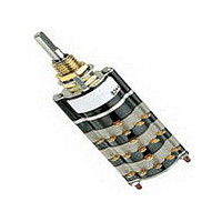
Rotary Switch,Standard, 36°
Manufacturer
Grayhill Inc
Datasheet
1.08A36-08-1-07N.pdf
(6 pages)
Specifications of 08A36-08-1-07N
Total # Of Positions
7
Pole Throw Configuration
SP
Actuator Style
Shaft
Actuator Material
Stainless Steel
Current Rating (max)
0.25A
Illumination Type
Not Required
Ac Voltage Rating (max)
115VVAC
Dc Voltage Rating (max)
28VVDC
Mechanical Life
50000
Contact Material
Silver Alloy
Contact Plating
Gold
Product Height (mm)
95.83mm
Product Depth (mm)
19.66mm
Product Length (mm)
19.66mm
Mounting Style
Panel
Terminal Type
Solder Lug
Lead Free Status / Rohs Status
Compliant


Available from your local Grayhill Distributor
CHOICES AND LIMITATIONS
Grayhill, Inc. • 561 Hillgrove Avenue • LaGrange, Illinois
ORDERING INFORMATION
Series
08
09
09A30–03–1–12N–F
* All rotary switches that are required to have military designated markings and testing adhering to MIL-3786 are to be ordered by specifying
the military part number identified on the appropriate slash sheet.
A = Standard
S = Standard, Shaft/Panel Seal
M = Military Style
MS = Style M, Shaft/Panel Seal
P = Standard, PC Mount
SP = Style P, Shaft/Panel Seal
MP = Military Style, PC Mount
MSP = Style MP, Shaft/Panel Seal
A = Standard
S = Standard, Shaft/Panel Seal
M = Military Style
MS = Style M, Shaft/Panel Seal
P = Standard, PC Mount
SP = Style P, Shaft/Panel Seal
MP = Military Style, PC Mount
MSP = Style MP, Shaft/Panel Seal
A = Standard,
S = Standard, Shaft/Panel Seal
M = Military Style
MS = Style M, Shaft/Panel Seal
A = Standard,
S = Standard, Shaft/Panel Seal
M = Military Style
MS = Style M, Shaft/Panel Seal
P = Standard, PC Mount
SP = Style P, Shaft/Panel Seal
MP = Military Style, PC Mount
MSP = Style MP, Shaft/Panel Seal
A = Standard
S = Standard, Shaft/Panel Seal
P = Standard, PC Mount
SP = Style, Shaft/Panel Seal
Style and Designation
Series: determined by the angle of throw
Style*: Letter(s) from the Choices and Limitations chart
Angle of Throw: Must agree with Series Number
Stop Arrangement: Add letter C or F to a one pole per deck switch with the maximum number of positions
for a stop between position 1 and the last position.
Type of Contacts: N = Non-shorting; S = Shorting
Positions Per Pole: Requires 02 positions as a minimum to the maximum allowable dependent on the angle
of throw and poles per deck
Poles Per Deck: As limited by angle of throw and switch style
Number of Decks: As limited by the angle of throw, the poles per deck, switch style and types of contacts
For prices and discounts, contact a Local Sales Office, an authorized local Distributor or Grayhill.
of Throw
Angle
36°
30°
45°
60°
90°
60525-5997 • USA • Phone: 708-354-1040 • Fax: 708-354-2820 • www.grayhill.com
Fixed
Fixed
Stops
Terminals
Printed
Printed
Printed
Printed
Solder
Circuit
Solder
Circuit
Solder
Circuit
Solder
Circuit
Multi-Deck Rotary Switches
01 thru 12
01 thru 09
01 thru 12
01 thru 09
01 thru 12
01 thru 09
01 thu 06
01 thru 04
01 thru 03
01 thru 03
01 thru 12
01 thru 09
01 thru 12
01 thru 06
01 thru 04
01 thru 03
Not
Available
Not
Available
Not
Available
Not
Available
Shorting
Number of Decks
Non-Shorting Per Deck
01 thru 03
01 thru 12
01 thru 09
01 thru 12
01 thru 09
01 thru 12
01 thru 09
01 thru 06
01 thru 04
01 thru 03
01 thru 03
01 thru 12
01 thru 09
01 thru 12
01 thru 06
01 thru 04
01 thru 03
01 thru 06
01 thru 03
01 or 02
01 thru 06
01 thru 06
01 thru 03
01 thru 06
01 thru 03
Poles
1
2
1
2
1
2
3
4
5
6
1
2
1
2
3
4
1
2
3
1
2
1
2
1
2
Positions/Pole
Number of
02 thru 10
02 thru 05
02 thru 10
02 thru 05
02 thru 12
02 thru 06
02 thru 04
02 or 03
02
02
02 thru 12
02 thru 06
02 thru 08
02 thru 04
02
02
02 thru 006
02 or 03
02
02 thru 06
02 or 03
02 thru 04
02
02 thru 04
02
Rotary
21
Related parts for 08A36-08-1-07N
Image
Part Number
Description
Manufacturer
Datasheet
Request
R

Part Number:
Description:
Rotary Switch,Standard, 36°
Manufacturer:
Grayhill Inc
Datasheet:
Part Number:
Description:
Rotary Switch,Standard, 36°
Manufacturer:
Grayhill Inc
Datasheet: