D2F-FL-A Omron, D2F-FL-A Datasheet
D2F-FL-A
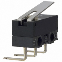
Specifications of D2F-FL-A
D2FFLA
SW841
Z2190
Z2190


Related parts for D2F-FL-A


D2F-FL-A Summary of contents
Page 1
... D2F-01-A 30VDC plunger 0.1A @ Pin D2F-01- A1 30VDC plunger 0.1A @ Pin D2F-01-D 30VDC plunger 0.1A @ Pin D2F-01-T 30VDC plunger 0.1A @ Pin D2F-01F 30VDC plunger D2F-01F- 0.1A @ Pin 30VDC plunger A 0.1A @ Pin D2F-01F- A1 30VDC plunger Contact Operating Seal type Termination form Force SPDT ...
Page 2
... Hinge D2F-FL- D 125VAC / lever 0.5A @ 30VDC D2F-FL Hinge T 125VAC / lever 0.5A @ 30VDC 3A @ Hinge D2F-L 125VAC/2A lever @ 30 VDC D2F-L Hinge 125VAC/2A lever @ 30 VDC 3A @ Hinge D2F-L- A1 125VAC/2A lever @ 30 VDC 3A @ Hinge D2F-L-D 125VAC/2A lever @ 30 VDC 3A @ Hinge D2F-L-T 125VAC/2A lever @ 30 VDC D2F-FL2 ...
Page 3
... D2F-01F-D D2F-01F-A D2F-01F-A1 D2F-01-D D2F-01-A D2F-01-A1 D2F-F-D D2F-F-A D2F-F-A1 D2F-D D2F-A D2F-A1 D2F-01FL-D D2F-01FL-A D2F-01FL-A1 D2F-01L-D D2F-01L-A D2F-01L-A1 D2F-FL-D D2F-FL-A D2F-FL-A1 D2F-L-D D2F-L-A D2F-L-A1 D2F-01FL3-D D2F-01FL3-A D2F-01FL3-A1 D2F-01L3-D D2F-01L3-A D2F-01L3-A1 D2F-FL3-D D2F-FL3-A D2F-FL3-A1 D2F-L3-D D2F-L3-A D2F-L3-A1 D2F-01FL2-D D2F-01FL2-A D2F-01FL2-A1 D2F-01L2-D D2F-01L2-A ...
Page 4
... C with no icing 45% to 85% ay 5° to 35° million operations min. (OT: full stroke) 30,000 operations min. (rated load) Approx. 0.5 g D2F-01FL-@, D2F-FL-@ D2F-01L-@, D2F-L — 0.55 mm (0.022 in) 0.5 mm (0.020 in) 6.8 ± 1.5 mm (0.267 ± 0.059 in ...
Page 5
... Contact Form ■ Approvals UL (File No. E41515), CSA (File No. LR21642), EN conforms 61058-1 Type Rating D2F Series, D2F-01 Series 3 A, 125 VAC 1 A, 125 VAC VDC 0 VDC 0 VDC Note: The rated values approved by each of the safety standards (e.g.UL,CSA) may be different from the performance characteristics individually defined in this catalog ...
Page 6
... Simulated Roller Lever D2F-01L3-@ D2F-01FL3-@ D2F-L3-@ D2F-FL3-@ ■ Roller Lever D2F-01L2-@ D2F-01FL2-@ D2F-L2-@ D2F-FL2-@ Note: 1. Unless otherwise specified, a tolerance of ± 0.4 mm applies to all dimensions. 2. Omitted dimensions are the same as pin plunger type. 3. Letters and numbers which identify the terminal are put in the blank box of the part number. ...
Page 7
... Terminals D2F type PCB terminal D2F-D type Soldered terminal D2F-A type Right-angle terminal D2F-T type Self-supporting terminal D2F-A1 type Left-angle terminal Snap Action Switch D2F 5 ...
Page 8
... Precautions ■ Mounting Mount the D2F switch onto the PC board as shown in the following diagram, using 2-pitch (2 x 2.54 mm) terminal spacing. ■ PC Board Machining ■ Dimensions The use of molded components is recommended for mounting pur- poses. ■ Molded Pin Mounting Diagram When screw mounting, use M2 screws together with washers. Fas- ten the screws applying 0 ...