704-030.218 EAO, 704-030.218 Datasheet - Page 3
704-030.218
Manufacturer Part Number
704-030.218
Description
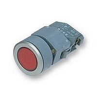
PUSHBUTTON SWITCH
Manufacturer
EAO
Datasheet
1.704-900.3.pdf
(38 pages)
Specifications of 704-030.218
Svhc
No SVHC (18-Jun-2010)
Approval Bodies
UL, CSA, SEV, NEMKO, GL
Colour
Red
Contact Voltage Ac Max
500V
External Depth
55mm
External Width
40mm
Ip/nema Rating
IP65
Main Contact Current Ac1 Max
10A
Lead Free Status / RoHS Status
Lead free / RoHS Compliant


Description
General Notes
The illuminated pushbuttons with 1 metre Immesion prooffront (IP 67)
combine the robust actuators of series 04 with gold plated silver
snap-action, low-level switching elements silver contacts for switch-
ing elements 2.8 mm plug-in terminals can be supplied on request for
1 changeover only.
The range includes pushbuttons, keylock switches and selector
switches.
Mounting
Mounting from the front through the mounting hole either 22.5 mm di-
ameter for raised or 30.5 mm diameter for flush.
The pushbuttons are screwed to the panel by means of a front ring
and prevented from twisting by two screws.
To ensure correct positioning of the pushbuttons we can provide a
positioning insert on request.
The universal terminals of the low-level switching elements permit
them to be mounted on printed circuit boards (PCB). These terminals
are also suitable for dip soldering. For these terminals we can also
supply a plug-in base which, when soldered on to the board, enables
the switch to be plugged in.
Lenses
The flat lenses, made of polyamide, are available in various colours,
as well as translucent or transparent.
Marking
For engravings, hot stamping and film inserts, see “Marking” on page
366.
Illumination
Perfect illumination of the different coloured lenses is assured by
lamps T 5,5 (6-60 V).
For supply voltages above 60 V, it is necessary to use a voltage re-
duction element (external series resistor, capacitor or transformer).
Do not solder the terminals directly, because of the high surface tem-
perature.
Multi-LEDs T 5,5 (6, 12, 24, 48 V) are available in the colours white,
red, yellow and green.
Position Indicating
When a switch with maintained action is actuated, the lens remains
in the depressed position mechanically. The state of the switch is ap-
parent at all times from the position of the lens.
All dimensions in mm.
We reserve the right to modify technical data.
Keylock switches
Safety lock (Index K).
Single locks (2 positions).
10 different locks with standard numbers 1001-1010. If the lock
number is not specified, we will supply No. 1001. An additional 690
locks with numbers 1011-1700 are available on request. For numbers
1001-1700 no master key can be supplied. Two keys are supplied
with each keylock switch.
Spare keys for KABA safety locks may be ordered by quoting
No. 14-987 (please state the lock number).
Combined locking systems
Information supplied on request.
Number structure
14-XXX.0XX
Example:
Specimen order
Indicator front illumination
- indicator front illumination,
Recommended accessories:
- lens plastic, opaque black 704.6020
- marking foil for lens plastic/metal black704.609.0
- frontring, aluminium black 704.6020
- LED. 1 chip, 12 VDC, white 10-2109.3139
soldering terminal 14-040.005
Kind of terminals
Contact material
Switch variant
-Illuminated pushbutton; momentary action,
gold-plated silver contact; soldering
terminals;1 switching element
14-131.025
-Lens red, transparent
704.602.2
-Front ring; aluminium, natural anodized
704.600.1
-Marking plate; white, translucent
704.609.9
01.2000
331
14
14
Related parts for 704-030.218
Image
Part Number
Description
Manufacturer
Datasheet
Request
R

Part Number:
Description:
Pushbutton Switch
Manufacturer:
EAO
Datasheet:
Part Number:
Description:
PUSHBUTTON,ILLUMINATED MBER COVER,SQUARE TOP 1-1/8",PANNEL MOUNT 7/8" HOLE.CMB1
Manufacturer:
EAO

Part Number:
Description:
Encoders 10k resisitve w/pushbutton
Manufacturer:
Electroswitch
Datasheet:
Part Number:
Description:
XLR Connectors NIKL/GOLD CABLE 3C
Manufacturer:
DEM Manufacturing
Datasheet:

Part Number:
Description:
Pushbutton Switch
Manufacturer:
EAO
Datasheet:
Part Number:
Description:
Pushbutton Switch
Manufacturer:
EAO
Datasheet:
Part Number:
Description:
Pushbutton Switch
Manufacturer:
EAO
Datasheet:


Part Number:
Description:
SINGLE CHIP LED/ T1 BI-PIN/ 2.1VDC/20MA - RED
Manufacturer:
EAO
Datasheet:

Part Number:
Description:
INDICATOR, INCAND LAMP, BI PIN
Manufacturer:
EAO
Datasheet:
Part Number:
Description:
INDICATOR, BI-PIN
Manufacturer:
EAO
Datasheet:

Part Number:
Description:
INDICATOR, INCAND LAMP, MIDGET GROOVED
Manufacturer:
EAO
Datasheet: