SPECIFICATIONS
Contact
Coil (at 25°C 77°F)
#1 This value can change due to the switching frequency, environmental conditions,
Remarks
* Specifications will vary with foreign standards certification ratings.
*
*
*
*
*
*
*
*
ORDERING INFORMATION
Type
Arrangement
Initial contact resistance, max.
(By voltage drop 6 V DC 1 A)
Contact material
Rating
(resistive)
Expected
life (min.
operations)
Nominal operating power
1
2
3
4
5
6
7
8
More than 10
side of contact pairs of each Form A contact and Form B contact
Measurement at same location as “Initial breakdown voltage” section
Detection current: 10mA
Excluding contact bounce time
Half-wave pulse of sine wave: 11ms; detection time: 10µs
Half-wave pulse of sine wave: 6ms
Detection time: 10µs
Refer to 6. Conditions for operation, transport and storage mentioned in
AMBIENT ENVIRONMENT
and desired reliability level, therefore it is recommended to check this with the
actual load.
2.098±.020
53.3±0.5
2: 2 Form A 2 Form B
3: 3 Form A 1 Form B
Contact arrangement
Ex. SF
5
Nominal switching
capacity
Max. switching power
Max. switching voltage
Max. carrying current
Min. switching capacity
Mechanical (at 180 cpm)
(resistive)
Electrical (at 20 cpm)
operations when applying the nominal switching capacity to one
2.098±.020
53.3±0.5
25.0
.984
2
16.5±0.5
.650±.020
mm
25.0
.984
#1
16.5±0.5
.650±.020
DC 5, 9, 12, 18, 21,
24, 36, 48, 60 V
DC 12 V
inch
All Rights Reserved © COPYRIGHT Matsushita Electric Works, Ltd.
POLARIZED, MONOSTABLE
Coil voltage
6 A 250 V AC, 6 A 30 V DC
(mechanical linked) forced
2 Form A
2 Form B
Gold-flashed silver alloy
SF2
30 V DC, 440 V AC
1,500 VA, 180 W
100 mA, 5 V DC
SAFETY RELAY with
6 A DC, AC
contacts operation
FEATURES
• Forced operation contacts (2 Form A
2 Form B, 3 Form A 1 Form B)
N.O. and N.C. side contacts are
connected through a card so that one
interacts with the other in movement. In
case of a contact welding, the other
keeps a min. 0.5mm
gap.
500 mW
3×10
30 mΩ
10
7
4
*
1
3 Form A
1 Form B
SF3
.020inch
Characteristics (at 20°C 68°F, 50% Relative humidity)
• Signal
• Escalator
• Elevator
• Medical Instruments
• Factory Automation
TYPICAL APPLICATIONS
Max. operating speed
Initial insulation resistance*
Initial
breakdown
voltage*
Operate time*
(at nominal voltage)
Release time (without diode)*
(at nominal voltage)
Temperature rise
(at nominal voltage)
Shock resistance
Vibration resistance
Conditions for
operation, transport
and storage*
condensing at low
temperature)
Unit weight
(Not freezing and
contact
3
Between contact sets
Between open contacts
Between contact and coil
8
4
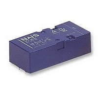
SF RELAYS
• Separated chamber structure
(2 Form A 2 Form B, 3 Form A
1 Form B)
N.O. and N.C. side contacts are put in
each own space surrounded with a card
and a body-separater. That prevents
short circuit between contacts, which is
caused by their springs welding or
damaged.
• UL/CSA, TÜV, SEV approved
Functional*
Destructive*
Functional*
Destructive
Ambient
temp.
Humidity
2
4
5
7
5
117.6 m/s
117.6 m/s
180 cpm (at nominal voltage)
with nominal coil voltage and
at double amplitude of 2 mm
at double amplitude of 2 mm
Min. 1,000 MΩ at 500 V DC
at 6 A switching current
Min. 980 m/s
Min. 294 m/s
SF2
–40°F to +158°F
–40°C to +70°C
5 to 85% R.H.
37 g
Max. 30 ms
Max. 15 ms
2,500 Vrms
2,500 Vrms
2,500 Vrms
Max. 45°C
2
2
{12 G}, 10 to 55 Hz
{12 G}, 10 to 55 Hz
1.31 oz
2
2
{100 G}
{30 G}
SF3
SF