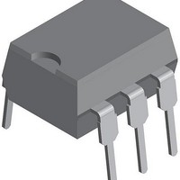
LH1550AT1 Vishay, LH1550AT1 Datasheet - Page 3

LH1550AT1
Manufacturer Part Number
LH1550AT1
Description
IC,Normally-Open PC-Mount Solid-State Relay,1-CHANNEL,DIP
Manufacturer
Vishay
Datasheet
1.LH1550AAB1TR.pdf
(6 pages)
Specifications of LH1550AT1
Load Voltage Rating
350 V
Load Current Rating
0.1 A
Contact Form
1 Form A
Output Device
MOSFET
Maximum Operating Temperature
+ 85 C
Minimum Operating Temperature
- 40 C
Package / Case
PDIP-6
Output Type
AC, DC
Mounting Style
Through Hole
Case Color
Black
Relay Type
Solid State
Lead Free Status / RoHS Status
Lead free / RoHS Compliant
Lead Free Status / RoHS Status
Lead free / RoHS Compliant, Lead free / RoHS Compliant
Available stocks
Company
Part Number
Manufacturer
Quantity
Price
Part Number:
LH1550AT1
Manufacturer:
SIEMENS/西门子
Quantity:
20 000
TYPICAL CHARACTERISTICS (T
Document Number: 83841
Rev. 1.7, 11-Mar-11
THE PRODUCT DESCRIBED HEREIN AND THIS DATASHEET ARE SUBJECT TO SPECIFIC DISCLAIMERS, SET FORTH AT
SAFETY AND INSULATION RATINGS
PARAMETER
Climatic classification
Pollution degree
Tracking resistance
(comparative tracking index)
Highest allowable overvoltage
Max. working insulation voltage
Insulation resistance at 25 °C
Insulation resistance at T
Insulation resistance at 100 °C
Partial discharge test voltage
Safety limiting values -
maximum values allowed
in the event of a failure
Minimum external air gap (clearance)
Minimum external tracking (creepage)
i1550_01
i1550at_00
100
Fig. 1 - Recommended Operating Conditions
1.6
1.5
1.4
1.3
1.2
1.1
1.0
80
60
40
20
0
- 40
- 40
Fig. 2 - LED Voltage vs. Temperature
I
I
I
I
I
Fon
Fon
Fon
F
F
= 1 mA
= 2 mA
= 2.0 mA
= 3.0 mA
= 4.5 to 20 mA
T
- 20
- 20
A
Ambient Temperature (°C)
- Ambient Temperature (°C)
I
0
0
F
S
I
= 20 mA
I
F
F
= 10 mA
= 5 mA
Case temperature
20
20
Output power
Input current
For technical questions, contact:
40
40
I
F
= 50 mA
60
60
amb
1 Form A High-Voltage Solid State
This datasheet is subject to change without notice.
80
= 25 °C, unless otherwise specified)
80
LH1550AAB1, LH1550AAB1TR, LH1550AT1
terminals, shortest distance path along body
Measured from input terminals to output
Measured from input terminals to output
terminals, shortest distance through air
Methode a, V
Recurring peak voltage
Transient overvoltage
Insulation group llla
TEST CONDITION
DIN VDE 0109
Relay
IEC 68 part 1
V
IO
pd
optocoupleranswers@vishay.com
= 500 V
= V
IORM
i1550at_02
i1550at_03
x 1.875
- 10
- 20
- 30
- 40
- 10
- 20
- 30
- 40
70
60
50
40
30
20
10
40
30
20
10
0
0
- 40
- 40
Fig. 4 - Turn-on Time vs. Temperature
Fig. 3 - Current Limit vs. Temperature
T
T
- 20
- 20
A
A
- Ambient Temperature (°C)
- Ambient Temperature (°C)
SYMBOL
Vishay Semiconductors
0
0
V
V
CTI
R
R
R
V
P
I
I
IORM
T
IOTM
I
F
L
pd
IS
IS
IS
SI
SO
SI
= 5 mA
= 50 mA
20
20
40
40
www.vishay.com/doc?91000
40/85/21
VALUE
10
10
10
8000
1669
I
t = 5 ms
175
890
175
300
700
7
7
F
2
60
60
= 5 mA
12
11
9
80
80
www.vishay.com
UNIT
V
V
V
mW
mm
mm
mA
peak
peak
peak
°C
3


