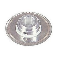
HEDS-5140#A05 Avago Technologies US Inc., HEDS-5140#A05 Datasheet - Page 8

HEDS-5140#A05
Manufacturer Part Number
HEDS-5140#A05
Description
Code-Wheel Encoder
Manufacturer
Avago Technologies US Inc.
Specifications of HEDS-5140#A05
Pulses Per Revolution
500
Rotational Speed Max
30000rpm
Frequency
100kHz
Mounting Type
3/16" Shaft Mount
Frequency Max
100kHz
Accessory Type
Code Wheel
Number Of Channels
3
Supply Voltage
5 V
Operating Temperature Range
- 40 C to + 100 C
Product
Optical
Size / Dimension
3/16 in
Encoder Resolution
500CPR
Rohs Compliant
Yes
For Use With
Optical Encoder Module
Lead Free Status / RoHS Status
Lead free / RoHS Compliant
Available stocks
Company
Part Number
Manufacturer
Quantity
Price
Mounting with an Alignment Tool
The HEDS-8905 and HEDS-8906 alignment tools are rec-
ommended for mounting the modules with Side B as the
mounting plane. The HEDS-8905 is used to mount the
HEDS-9140, and the HEDS-8906 is used to mount the
HEDS-9040. These tools fi x the module position using
the codewheel hub as a reference. They will not work if
Side A is used as the mounting plane.
The following assembly procedure uses the HEDS-
8905/8906 alignment tool to mount a HEDS-9140/9040
module and a HEDS-5140/6140 codewheel:
Instructions:
1. Place codewheel on shaft.
2. Set codewheel height by placing alignment tool
3. Insert mounting screws through module and thread
4. Slide alignment tool over codewheel hub and onto
5. While holding alignment tool in place, tighten screws
6. Remove alignment tool.
Mounting with Aligning Pins
The HEDS-9040 and HEDS-9140 can also be mounted us-
ing aligning pins on the motor base. (Hewlett-Packard
does not provide aligning pins.) For this confi guration,
Side A must be used as the mounting plane. The align-
ing recess centers must be located within the 0.005 in. R
Tolerance Circle as explained above. Figure 5 shows the
necessary dimensions.
8
on motor base (pins facing up) fl ush up against the
codewheel as shown in Figure 3. Tighten codewheel
setscrew and remove alignment tool.
into the motor base. Do not tighten screws.
module as shown in Figure 4. The pins of the alignment
tool should fi t snugly inside the alignment recesses of
the module.
down to secure module.
Figure 3. Alignment Tool is Used to Set Height of Codewheel.
Figure 4. Alignment Tool is Placed over Shaft and onto Codewheel Hub.
Alignment Tool Pins Mate with Aligning Recesses on Module.


