TH-K-1-0-5 Simpson, TH-K-1-0-5 Datasheet - Page 3
TH-K-1-0-5
Manufacturer Part Number
TH-K-1-0-5
Description
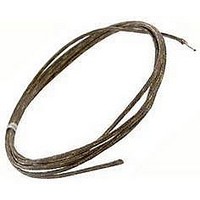
Thermocouple Cable
Manufacturer
Simpson
Type
K Typer
Specifications of TH-K-1-0-5
Length
5ft
Cable Type
Fibre Glass Braid
Leaded Process Compatible
No
Peak Reflow Compatible (260 C)
No
Terminal Type
Screw
Probe Length
60 In
Function
Thermocouple
Primary Type
Temperature
Technology
Resistive
Accessory Type
Thermocouple Cable
Rohs Compliant
No
For Use With
Falcon F45 Series Digital Panel Meter
Lead Free Status / RoHS Status
Contains lead / RoHS non-compliant


1) Disconnect all wires from terminal block.
2) Remove front bezel.
3) Slide internal meter out front of unit (it is easier to leave case
mounted in the panel).
THERMOCOUPLE OR RTD SELECTION
The thermocouple or RTD selection is made by placing push-on jump-
ers at the designated positions on the main board. See the table and
diagram to the right for location and placement.
EXAMPLE 1: To configure the meter for a J type thermocouple, no
jumpers are required on JU6, JU7, JU8, or JU9. A push-on jumper is
positioned on JU10 only.
EXAMPLE 2: To configure the meter for a 3-wire RTD, push-on jump-
ers are positioned on JU9 and JU10 only. No jumpers are required on
JU6, JU7, or JU8.
NOTE: Additional jumpers are included for alternate range and scal-
ing selections.
side of the display (see diagram). Push-on jumpers (on JU1 and JU2) are
used to make your selection. The Fahrenheit / Celsius unit of measure-
ment is selected by using jumper JU2, and the resolution of the meter is
determined by using jumper JU1. You can select a resolution of either
0.1º or 1.0 º for thermocouple types J, K, T, E or RTD sensors only. Due
to inherent characteristics, types R and S must have 1.0º resolution.
JU1 is also used to select mV resolution.
Thermocouple and RTD selections are made on the main board as
shown in the table and diagram to the right.
To gain access to the main board and the display board, the meter
must be opened. Use the following procedure:
UNIT MEASUREMENT AND RESOLUTION
These selections are made on the display board, located on the front left
0.1º, .001mV
1º, .01mV
Setup
Function Setup and Range
When connecting the ancillary device, ensure that DGND and the ancillary device are at
the same potential, or are properly isolated. Failure to do so may result in equipment
damage or undesirable ground loops.
RESOLUTION
Disconnect power supply and all connections
Jumper JU1
OUT
before opening case.
IN
ºC
ºF
ºF/ ºC SELECT
Jumper JU2
OUT
IN
2 wire RTD
3 wire RTD
4 wire RTD
Display Hold
This standard feature allows you to hold the displayed value indefinitely.
To activate this feature, create a short circuit across jumpers # 5 and #6
with an ancillary device (such as a switch or computer). To restore the
meter to normal display mode, remove the short circuit. This connection
must be kept isolated from other circuitry. To hold multiple units, separate
poles of the switch must be used to maintain the isolation.
Sensor
Type
mV
K
E
R
S
J
T
JU 6
OUT
OUT
OUT
OUT
OUT
OUT
IN
IN
IN
IN
JU 7
OUT
OUT
OUT
OUT
OUT
OUT
OUT
IN
IN
IN
RTD SENSORS
Thermocouple
Jumper Identification
J104 REMOVE THIS JUMPER
ONLY WHEN RECALIBRATING
THE UNIT.
JU 8
OUT
OUT
OUT
OUT
OUT
OUT
OUT
IN
IN
IN
JU 9
OUT
OUT
OUT
OUT
OUT
OUT
IN
IN
IN
IN
JU 10
OUT
IN
IN
IN
IN
IN
IN
IN
IN
IN
Related parts for TH-K-1-0-5
Image
Part Number
Description
Manufacturer
Datasheet
Request
R

Part Number:
Description:
Thermocouple Cable
Manufacturer:
Simpson
Datasheet:

Part Number:
Description:
Electromechanical Hour Meter
Manufacturer:
Simpson
Datasheet:

Part Number:
Description:
Electromechanical Hour Meter
Manufacturer:
Simpson
Datasheet:

Part Number:
Description:
Electromechanical Hour Meter
Manufacturer:
Simpson
Datasheet:

Part Number:
Description:
Electromechanical Hour Meter
Manufacturer:
Simpson
Datasheet:

Part Number:
Description:
Electromechanical Hour Meter
Manufacturer:
Simpson
Datasheet:
Part Number:
Description:
SIGNAL CONDITIONING,EXTERNAL PORTABLE AND SWITCHBOARD SHUNTS,SIGNAL CONDITIONING,SIGNAL CONDITIONING, OUTPUT CURRENT RATING 100 AMPERE,METERS,EXTERNAL PORTABLE AND SWITCHBOARD SHUNTS ,SIMPSON
Manufacturer:
Simpson
Datasheet:
Part Number:
Description:
SIMPSON MODEL 12211 260-6XLPM VOM, LOW POWER OHMS, CALIBRATED
Manufacturer:
Simpson
Part Number:
Description:
Analog Panel Meters 1349 0-50 ACV-RE
Manufacturer:
Simpson
Datasheet:
Part Number:
Description:
Analog Panel Meters 2121 25-0-25 DCUA
Manufacturer:
Simpson
Datasheet:
Part Number:
Description:
ANALOG FREQUENCY METER
Manufacturer:
Simpson
Datasheet:
Part Number:
Description:
TERMINAL,PIDG R 12-10 1/4
Manufacturer:
Simpson
Datasheet: