R158-0/1000AK.42RB HENGSTLER, R158-0/1000AK.42RB Datasheet - Page 49
R158-0/1000AK.42RB
Manufacturer Part Number
R158-0/1000AK.42RB
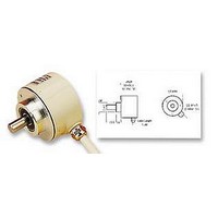
Description
ENCODER, ROTARY
Manufacturer
HENGSTLER
Datasheet
1.RI32-01000ER.14KB.pdf
(61 pages)
Specifications of R158-0/1000AK.42RB
No. Of Input Channels
3
Rotational Speed Max
10000rpm
Body Diameter
58.5mm
Connector Type
Cable
Current Consumption
60mA
Encoder Resolution
1000
External Length / Height
35.5mm
Lead Length
1.5m
No. Of Channels
3
Svhc
No SVHC (15-Dec-2010)


MOUNTING NECESSITIES
CONNECTION DIAGRAM
CABLE PVC
CONNECTION DIAGRAM
CABLE TPE
E N C O D E R S C O U N T E R S C O N T R O L L E R S I N D I C A T O R S R E L A Y S P R I N T E R S C U T T E R S
Incremental Shaft Encoders
with Hollow Shaft
In order to be able to compensate an axial and radial misalignment of the shaft, the encoder
flange must not be fixed rigidly.
Fix the flanges by means of a stator coupling (e.g. spring plate) as torque support (see
“Accessories”) or by means of a cylindrical pin:
Mounting D, F (Clamping shaft)
Preparation of the machine flange1)
(all mounting versions):
In the machine flange a straight pin must
be installed (diameter 4x16 resp. 4x20,
DIN 6325).
This pin is required as a torque support.
1)
1)
1)
2)
Cable PVC
Colour
white
white/brown
green
green/brown
yellow
yellow/brown
yellow/black
yellow/red
red
black
Cable screen
Cable TPE
Colour
brown
green
grey
pink
red
black
violet (white)
blue
brown/green
white/green
Cable screen
Dimensions in mm also apply for shaft-ø 10 or 14
Or as an option: stator coupling as torque support
connected to housing
connected to housing
white with Version Sense (T)
1)
1)
2)
RS 422
+ Sense (T)
Channel A
Channel A
Channel B
Channel B
Channel N
Channel N
Sense GND
Sense V
5 V DC=
GND
Cable screen
RS 422
+ Sense (T)
Channel A
Channel A
Channel B
Channel B
Channel N
Channel N
Sense GND
Sense V
5 V DC=
GND
Cable screen
CC
CC
1)
1)
Output circuit
RS 422
+ Alarm (R)
Channel A
Channel A
Channel B
Channel B
Channel N
Channel N
Alarm
Sense V
5/10…30 V DC=
GND
Cable screen
Output circuit
RS 422
+ Alarm (R)
Channel A
Channel A
Channel B
Channel B
Channel N
Channel N
Alarm
Sense V
5/10…30 V DC=
GND
Cable screen
CC
CC
Mounting E (Blind shaft)
Preparation of the drive shaft
(only in mounting = E):
The drive shaft must be provided with a
threaded bore M 4 x10:
This bore accepts the fastening screw of the
shaft encoder.
1)
1)
Dimensions in mm also apply for shaft-ø 10 or 14
push-pull (K)
Channel A
Channel B
Channel N
Alarm
10…30 V DC=
GND
Cable screen
push-pull (K)
Channel A
Channel B
Channel N
Alarm
10…30 V DC=
GND
Cable screen
Shaft Encoders 2001
Type RI 58-D
1)
1)
push-pull
complementary (I)
Channel A
Channel A
Channel B
Channel B
Channel N
Channel N
Alarm
Sense V
10…30 V DC=
GND
Cable screen
push-pull
complementary (I)
Channel A
Channel A
Channel B
Channel B
Channel N
Channel N
Alarm
Sense V
10…30 V DC=
GND
Cable screen
CC
CC
1)
1)
91
Related parts for R158-0/1000AK.42RB
Image
Part Number
Description
Manufacturer
Datasheet
Request
R

Part Number:
Description:
ENCODER, ROTARY
Manufacturer:
HENGSTLER
Datasheet:
Part Number:
Description:
ENCODER, ROTARY
Manufacturer:
HENGSTLER
Datasheet:

Part Number:
Description:
ENCODER, ROTARY
Manufacturer:
HENGSTLER
Datasheet:

Part Number:
Description:
ENCODER, ROTARY
Manufacturer:
HENGSTLER
Datasheet:
Part Number:
Description:
ENCODER, ROTARY
Manufacturer:
HENGSTLER
Datasheet:
Part Number:
Description:
ENCODER, ROTARY
Manufacturer:
HENGSTLER
Datasheet:
Part Number:
Description:
ENCODER, ROTARY
Manufacturer:
HENGSTLER
Datasheet:

Part Number:
Description:
ENCODER, INCREMENTAL
Manufacturer:
HENGSTLER
Datasheet:
Part Number:
Description:
ENCODER, ROTARY
Manufacturer:
HENGSTLER
Datasheet:
Part Number:
Description:
ENCODER, ROTARY
Manufacturer:
HENGSTLER
Datasheet:

Part Number:
Description:
HIGH VOLTAGE SURFACE MOUNT MLCCS 250 - 5,000 VDC
Manufacturer:
Johanson Dielectrics
Part Number:
Description:
Olympian Filter
Manufacturer:
Norgren
Datasheet:
Part Number:
Description:
Industrial Relays Of Small Dimensions
Manufacturer:
ZETTLER Electronics Inc.
Datasheet: