E3XNA8 Omron, E3XNA8 Datasheet - Page 16
E3XNA8
Manufacturer Part Number
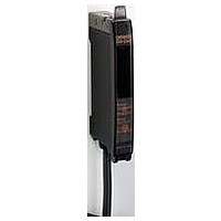
E3XNA8
Description
Photoelectric Sensor
Manufacturer
Omron
Type
Standard Fiber Optic Sensorr
Datasheet
1.E3XNA6.pdf
(28 pages)
Specifications of E3XNA8
Sensor Output
PNP
Sensor Input
Fiber Optic
Output Type
PNP LO/DO
Supply Voltage Max
24V
Switch Terminals
Connector
Supply Voltage Min
12V
Fiber Optic Sensor Type
Standard Fiber Optic Sensor
Rohs Compliant
Yes
Lead Free Status / RoHS Status
Lead free / RoHS Compliant


E3X-NA
I
Depending on how it is mounted, an Amplifier Unit may move
during operation. In this case, use an End Plate.
Before mounting an End Plate, remove the clip from the master
Amplifier Unit using a nipper or similar tool.
The clip can also be removed using the following mechanism,
which is incorporated in the construction of the section under-
neath the clip.
1.
2. Remove the clip by rotating the Amplifier Unit.
Pull Strengths for Connectors (Including Cables)
E3X-CN11: 30 N max.
E3X-CN12: 12 N max.
16
Mounting End Plate (PFP-M)
Insert the clip that is to be removed into the slit underneath
the clip on another Amplifier Unit.
Rotate
Clip
I
Use of E39-R3 Reflector
Use detergent, etc., to remove any dust or oil from the surfaces
where tape is applied. Adhesive tape will not be attached properly
if oil or dust remains on the surface.
The E39-R3 cannot be used in places where it is exposed to oil or
chemicals.
E39-F32
Insert a fiber to the Protective Spiral Tube from the head connec-
tor side (screwed) of the tube.
Push the fiber into the Protective Spiral Tube. The tube should be
straight so that the fiber is not twisted when inserted. Then turn
the end cap of the spiral tube.
Secure the Protective Spiral Tube on a suitable place with the
attached nut.
Use the attached saddle to secure the end cap of the Protective
Spiral Tube. To secure the Protective Spiral Tube at a position
other than the end cap, apply tape to the tube so that the portion
becomes thicker in diameter.
I
Mount the Fiber Connector as shown in the following illustrations.
The Fiber Units should be as close as possible when they are
connected.
Sensing distance will be reduced by approximately 25% when
fibers are connected.
Only 2.2-mm-dia. fibers can be connected.
Fiber Unit
Reflector
E39-F10 Fiber Connector
Retention unit
@
Tube
Protective Spiral Tubes
Protective Spiral
Tube
Saddle
Mounting panel
End cap
Protective Spiral
Tube
Splice
Protective Spiral
Tube
Fiber Unit
Retention unit
Toothed washer
Hexagon clamping nut
Fiber Unit
Fiber Unit
Fiber Unit
Fiber Unit
E3X-NA
Fiber Unit
Related parts for E3XNA8
Image
Part Number
Description
Manufacturer
Datasheet
Request
R

Part Number:
Description:
G6S-2GLow Signal Relay
Manufacturer:
Omron Corporation
Datasheet:
Part Number:
Description:
Compact, Low-cost, SSR Switching 5 to 20 A
Manufacturer:
Omron Corporation
Datasheet:
Part Number:
Description:
Manufacturer:
Omron Corporation
Datasheet:
Part Number:
Description:
Manufacturer:
Omron Corporation
Datasheet:
Part Number:
Description:
Manufacturer:
Omron Corporation
Datasheet:
Part Number:
Description:
Manufacturer:
Omron Corporation
Datasheet:
Part Number:
Description:
Manufacturer:
Omron Corporation
Datasheet:
Part Number:
Description:
Manufacturer:
Omron Corporation
Datasheet: