ASF1400 SENSIRION, ASF1400 Datasheet - Page 6
ASF1400
Manufacturer Part Number
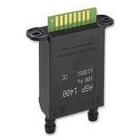
ASF1400
Description
SENSOR, MASS FLOW
Manufacturer
SENSIRION
Datasheet
1.ASF1400.pdf
(11 pages)
Specifications of ASF1400
Pressure Max
120Pa
Supply Voltage Range Dc
7V To 18V
Accuracy
± 1%
Air Mass Flow Range
-400sccm To 400sccm
Svhc
No SVHC (15-Dec-2010)
Connection Size
5mm
Measuring Range
.015 To 400 Sscm
Supply Voltage Dc
RoHS Compliant
Response Time
142ms
Rohs Compliant
Yes


ASF1400 Bidirectional Mass Flow Meter
SCK
The SCK synchronizes data transfer out of the device
through the MOSI line. Data on the MOSI pin is ready
after a falling edge of SCK (see Figure 9 and 10 for
details).
/CS
There are two SPI modes, namely the PUSH and the GET
mode. In PUSH mode the /CS pin is controlled by the
ASF1400 device which behaves like a master. Low going
/CS announces a new data transfer (see also Section 4.3).
In GET mode the data transfer is initiated externally by
pulling /CS low. In this case, as soon as the measurement
data is ready, it appears on the MOSI pin.
MOSI
MOSI is the serial data output of the ASF1400 device. Data
is clocked out on the rising edge SCK with MSB first. This
output goes into a high-impedance state when the device is
not selected.
MISO
The ASF1400 firmware only supports a uni-directional SPI
protocol. Therefore, the MISO pin should always left
unconnected.
3
The ASF1400 device accepts a set of commands through
its RS-232 interface (see table 3 for valid commands; for
correct settings of the RS-232 refer to Section 2.1).This
allows the user to configure the ASF1400 device. Since the
configuration is stored in the internal EEPROM, it is
maintained after power breaks.
Table 3: Commands of the ASF1400 device.
Notes:
• Default settings are marked in bold letters
• The commands are not case sensitive.
www.sensirion.com
Command
help↵
ver↵
get↵
go↵
s
reset↵
res=1..9↵
res?
mod=F | T↵
mod?
Disp=s,d
Disp?
defspi=P | G↵
Configuration and Commands
(Master In Slave Out, Not Connected)
(Serial Clock, Output)
(Chip Select, Input or Output)
(Master Out Slave In, Output)
Output
commands
version
stop
resolution
resolution
mode
mode
display mode
display mode
define spi
Description
Lists all available commands
Provides type of sensor, software, hardware and customer version
Start single measurement
Starts series of measurements
Stops series of measurements
Resets ASF1400 device
Sets resolution: 1 -> 12 bits; 9 -> 15 bits, see Table 2
Shows actual setting
Selects Flow- (F) or Temperature mode (T)
Shows actual setting
Shows Flow (s) or Flow+Temperature (d)
Shows actual setting
Sets SPI in Push- (P) or Get mode (G), see also Section 4.3
Version 2.1
With the exception of the stop s command, all commands
have to be terminated by the return key (↵, ASCII #10 or
#13). After completion of a command, the ASF1400 returns
ok and is ready to take a new instruction. Before entering a
command, it may be necessary to clear the buffer by
means of using ↵.
There is a trade-off between resolution and measurement
time. Possible settings are listed in Table 2. Choosing 12
bit results in a measurement interval of 142 ms. With the
max resolution of 15.2 bit, a new measurement is provided
every 1280 ms. For faster sampling rates refer to the
ASF1430 high speed mass flow meter device data sheet.
Table 2: Resolution settings using the res=value command
and corresponding response times
res=
1
2
3
4
5
6
7
8
9
Resolution [bit]
*no effect in the Temerature mode
12.0
13.0
13.5
14.0
14.3
14.6
14.8
15.0
15.2
data interval [ms]
1138
1280
142
284
427
569
711
853
995
6/11
Related parts for ASF1400
Image
Part Number
Description
Manufacturer
Datasheet
Request
R


Part Number:
Description:
MODULE SENSOR TEMP+HUMIDITY
Manufacturer:
Parallax Inc
Datasheet:

Part Number:
Description:
Humidity Sensor Filter Cap
Manufacturer:
SENSIRION
Datasheet:

Part Number:
Description:
Sensor Evaluation Kit
Manufacturer:
SENSIRION
Datasheet:

Part Number:
Description:
Sensor Evaluation Kit
Manufacturer:
SENSIRION
Datasheet:
Part Number:
Description:
Sensor Evaluation Kit
Manufacturer:
SENSIRION
Datasheet:
Part Number:
Description:
Sensor Evaluation Kit
Manufacturer:
SENSIRION
Datasheet:

