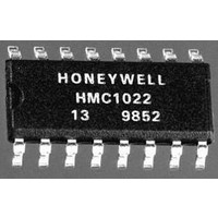
HMC1022 Honeywell Microelectronics & Precision Sensors, HMC1022 Datasheet - Page 7

HMC1022
Manufacturer Part Number
HMC1022
Description
Magnetic Sensor
Manufacturer
Honeywell Microelectronics & Precision Sensors
Datasheets
1.HMC1021.pdf
(15 pages)
2.HMC1022.pdf
(15 pages)
3.HMC1022.pdf
(15 pages)
4.HMC1022.pdf
(15 pages)
Specifications of HMC1022
Sensitivity Range
1mV/V/G
Sensor Output
Voltage
Terminal Type
PCB Thru Hole
Output Type
Differential
Sensor Terminals
SMD Gull Wing
Leaded Process Compatible
No
Magnetic Field Max
6G
Axis Configuration
Two
Lead Free Status / RoHS Status
Lead free / RoHS Compliant
Available stocks
Company
Part Number
Manufacturer
Quantity
Price
Company:
Part Number:
HMC1022
Manufacturer:
honeywell
Quantity:
12 800
Part Number:
HMC1022
Manufacturer:
HONEYWE
Quantity:
20 000
Part Number:
HMC1022-TR
Manufacturer:
HITTITE
Quantity:
20 000
NOISE CHARACTERISTICS
The noise density curve for a typical MR sensor is shown
in Figure 3. The 1/f slope has a corner frequency near 10
Hz and flattens out to 3.8 nV/√Hz. This is approximately
equivalent to the Johnson noise (or white noise) for an
850Ω resistor—the typical bridge resistance. To relate the
noise density voltage in Figure 3 to the magnetic fields, use
the following expressions:
For the noise components, use the following expressions:
WHAT IS OFFSET STRAP?
Any ambient magnetic field can be canceled by driving a
defined current through the OFFSET strap. This is useful
for eliminating the effects of stray hard iron distortion of the
earth’s magnetic field. For example, reducing the effects of
a car body on the earth’s magnetic field in an automotive
compass application. If the MR sensor has a fixed position
within the automobile, the effect of the car on the earth’s
magnetic field can be approximated as a shift, or offset, in
this field. If this shift in the earth's field can be determined,
1 0 0 0
1 0 0
For Vsupply=5V and Sensitivity=3.2mV/V/gauss,
Bridge output response =
The noise density at 1Hz ≈ 30nV/√Hz
white noise (BW=1KHz) =
1 0
1
0 . 1
1/f noise(0.1-10Hz) =
Figure 3—Typical Noise Density Curve
and corresponds to
1
(1001/1002)
or
Frequency
1 0
16 mV/gauss
16 nV/µgauss
1.8 µgauss/√Hz
30 * √(ln(10/.1)) nV
64 nV (rms)
4 µgauss (rms)
27 µgauss (p-p)
3.8 * √BW nV
120 nV (rms)
50 µgauss (p-p)
(Hz)
1 0 0
1 0 0 0
LINEAR MAGNETIC FIELD SENSORS
7
then it can be compensated for by applying an equal and
opposite field using the OFFSET strap. Another use for the
OFFSET strap would be to drive a current through the strap
that will exactly cancel out the field being measured. This is
called a closed loop configuration where the current feedback
signal is a direct measure of the applied field.
The field offset strap (OFFSET+ and OFFSET-) will generate
a magnetic field in the same direction as the applied field
being measured. This strap provides a 1 Oersted (Oe) field
per 50 mA of current through it in HMC1001/2 and 1 Oe/5mA
in HMC1021/2. (Note: 1 gauss=1 Oersted in air). For
example, if 25 mA were driven from the OFFSET+ pin to the
OFFSET- pin in HMC1001/2, a field of 0.5 gauss would be
added to any ambient field being measured. Also, a current
of -25 mA would subtract 0.5 gauss from the ambient field.
The OFFSET strap looks like as a nominal resistance
between the OFFSET+ and OFFSET- pins.
The OFFSET strap can be used as a feedback element in
a closed loop circuit. Using the OFFSET strap in a current
feedback loop can produce desirable results for measuring
magnetic fields. To do this, connect the output of the bridge
amplifier to a current source that drives the OFFSET strap.
Using high gain and negative feedback in the loop, this will
drive the MR bridge output to zero, (OUT+) = (OUT-). This
method gives extremely good linearity and temperature
characteristics. The idea here is to always operate the MR
bridge in the balanced resistance mode. That is, no matter
what magnetic field is being measured, the current through
the OFFSET strap will cancel it out. The bridge always
“sees” a zero field condition. The resultant current used to
cancel the applied field is a direct measure of that field
strength and can be translated into the field value.
The OFFSET strap can also be used to auto-calibrate the
MR bridge while in the application during normal operation.
This is useful for occasionally checking the bridge gain for
that axis or to make adjustments over a large temperature
swing. This can be done during power-up or anytime during
normal operation. The concept is simple; take two point
along a line and determine the slope of that line—the gain.
When the bridge is measuring a steady applied magnetic
field the output will remain constant. Record the reading for
the steady field and call it H1. Now apply a known current
through the OFFSET strap and record that reading as H2.
The current through the OFFSET strap will cause a change
in the field the MR sensor measures—call that delta applied
field (∆Ha). The MR sensor gain is then computed as:
There are many other uses for the OFFSET strap than those
described here. The key point is that ambient field and the
OFFSET field simply add to one another and are measured
by the MR sensor as a single field.
MRgain = (H2-H1) / ∆Ha


