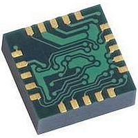
HMC5843 Honeywell Microelectronics & Precision Sensors, HMC5843 Datasheet - Page 9

HMC5843
Manufacturer Part Number
HMC5843
Description
Magnetic Sensor
Manufacturer
Honeywell Microelectronics & Precision Sensors
Datasheet
1.HMC5843.pdf
(21 pages)
Specifications of HMC5843
Msl
MSL 3 - 168 Hours
Sensitivity Range
+/- 10 %
Sensor Terminals
PCB
Magnetic Field Max
4G
Axis Configuration
Three
Sensor Output
Digital
Available stocks
Company
Part Number
Manufacturer
Quantity
Price
Company:
Part Number:
HMC5843
Manufacturer:
HITTITE
Quantity:
3 000
Company:
Part Number:
HMC5843-DEMO
Manufacturer:
Honeywell Microelectronics & P
Quantity:
135
Company:
Part Number:
HMC5843-EVAL
Manufacturer:
Honeywell Microelectronics & P
Quantity:
135
HMC5843
Charge Current Limit
The current that reservoir capacitor (C1) can draw when charging is limited. When using dual supplies this device shall
limit the current drawn from DVDD source to charge this capacitor. When only a single supply is used, Pin DVDD is
externally tied to pin C1. In this configuration, current is still limited. For example, the internal voltage regulator will limit
this current draw.
Bias Current Generator
The bias current generator is used to apply a bias current to the offset strap of the magneto-resistive sensor, which
creates an artificial magnetic field bias on the sensor. This function is enabled and the polarity is set by bits MS[n] in the
configuration register. The bias current generator generates dc current supplied from the AVDD supply.
MODES OF OPERATION
This device has several modes whose primary purpose is power management. This section describes these modes.
Continuous-Measurement Mode
During continuous-measurement mode, the device continuously makes measurements and places measured data in data
output registers.
Settings in the configuration register affect the data output rate (bits DO[n]), the measurement
configuration (bits MS[n]), the gain (bits GN[n]), and the delay (bits DL[n]) when in continuous-measurement mode. To
conserve current between measurements, the device is placed in a state similar to idle mode, but the mode is not
changed to idle mode. That is, MD[n] bits are unchanged.
Data can be re-read from the data output registers if
necessary; however, if the master does not ensure that the data register is accessed before the completion of the next
measurement, the new measurement may be lost. All registers maintain values while in continuous -measurement mode.
2
The I
C bus is enabled for use by other devices on the network in while continuous-measurement mode.
Single-Measurement Mode
This is the default single supply power-up mode. In dual supply configuration this is the default mode when AVDD goes
high. During single-measurement mode, the device makes a single measurement and places the measured data in data
output registers. Settings in the configuration register affect the measurement configuration (bits MS[n]), the gain (bits
GN[n]), and the delay (bits DL[n]) when in single-measurement mode. After the measurement is complete and output
data registers are updated, the device is placed sleep mode, and the mode register is changed to sleep mode by setting
2
MD[n] bits. All registers maintain values while in single-measurement mode. The I
C bus is enabled for use by other
devices on the network while in single-measurement mode.
Idle Mode
2
During this mode the device is accessible through the I
C bus, but major sources of power consumption are disabled,
such as, but not limited to, the ADC, the amplifier, the SVDD pin, and the sensor bias current. All registers maintain
2
values while in idle mode. The I
C bus is enabled for use by other devices on the network while in idle mode.
Sleep Mode
This is the default dual supply power-up mode when only DVDD goes high and AVDD remains low. During sleep mode
2
the device functionality is limited to listening to the I
C bus. The internal clock is not running and register values are not
maintained while in sleep mode. The only functionality that exists during this mode is the device is able to recognize and
2
execute any instructions specific to this device but does not change from sleep mode due to other traffic on the I
C bus.
2
The I
C bus is enabled for use by other devices on the network while in sleep mode. This mode has two practical
differences from idle mode. First this state will create less noise on system since the clock is disabled, and secondly this
state is a lower current consuming state since the clock is disabled.
Off Mode
2
During off mode device is off. No device functionality exists. Both AVDD and DVDD are low. The I
C bus is enabled for
2
use by other devices on the network in off mode. In this mode the I
C pins shall be in a high impedance state.
www.honeywell.com
9


