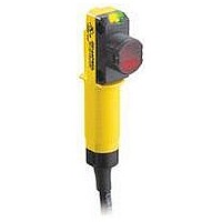
QS18ANWLP BANNER ENGINEERING, QS18ANWLP Datasheet - Page 3

QS18ANWLP
Manufacturer Part Number
QS18ANWLP
Description
Photoelectric Sensor
Manufacturer
BANNER ENGINEERING
Type
Retroreflectiver
Datasheet
1.QS18ANWDL.pdf
(4 pages)
Specifications of QS18ANWLP
Output Current
100mA
Sensor Output
MOSFET
Sensor Housing
Cylindrical
Sensor Input
Optical
Body Material
ABS
Supply Voltage Max
270V
Sensing Range Max
3.5m
Contact Current Max
10mA
Switch Terminals
Cable
Brand/series
QS18 Series
Current Rating
100 mA
Current, Switching
100 mA
Dimensions
80.5 × 15 × 34.0 mm
Function
Proximity
Indicator
LED
Ip Rating
IP67
Material, Body
ABS
Material, Lens
PMMA
Mounting Type
Panel
Output
N-MOSFET
Primary Type
Photoelectric
Range, Measurement
3.5 m
Repeatability
1.5 ms
Sensing Mode
Polar Retro Visible Red
Sensor Type
Voltage
Standards
cULus Recognized, CE Approved
Technology
Photoelectric
Temperature, Operating
–25 to 70 °C
Termination
Cable
Voltage, Supply
20-270 VAC/VDC
Lead Free Status / Rohs Status
RoHS Compliant part
750 mm
500 mm
250 mm
250 mm
500 mm
750 mm
G
N
E
X
C
E
S
S
A
X
C
S
S
G
A
N
I
Banner Engineering Corp. • Minneapolis, MN U.S.A
E
E
I
1000
1000
www.bannerengineering.com • Tel: 763.544.3164
100
0
100
10
10
0.01 m
1
0.03 ft
0.01 m
0
1
0.03 ft
Opposed Mode
QS186E and QS18...R
1
4
3
1
3
P-MOSFET — Cable
N-MOSFET — Cable
1
4
3
12 ft
Excess Gain
4 m
Emitter — Cable
0.33 ft
0.33 ft
0.1 m
0.1 m
with BRT-84 Reflector
DISTANCE
26 ft
DISTANCE
8 m
DISTANCE
with BRT-84 Reflector
Retroreflective Mode
Load
Retroreflective Mode
Load
QS18...LV
12 m
40 ft
QS18...LP
3.3 ft
3.3 ft
1 m
1 m
16 m
52 ft
10 m
33 ft
10 m
33 ft
L1 (DC+)
L2 (DC–)
20 m
66 ft
L1 (DC+)
L2 (DC–)
L1 (DC+)
L2 (DC–)
30 in
20 in
10 in
0
10 in
20 in
30 in
750 mm
500 mm
250 mm
250 mm
500 mm
750 mm
150 mm
100 mm
100 mm
150 mm
30 mm
20 mm
10 mm
10 mm
20 mm
30 mm
50 mm
50 mm
0
0
0
0
0
0
Retroreflective Mode
Opposed Mode
QS186E and QS18...R
QS18...LP
.75 m
2.5 ft
QS18...LV
Beam Pattern
1.5 m
12 ft
4 m
5 ft
with BRT-84 Reflector
Retroreflective Mode
with BRT-84 Reflector
Key — Cable
1 = Brown
3 = Blue
4 = Black†
† No connection
1.5 m
for emitters
5 ft
3.0 m
1 = Brown
3 = Blue
4 = Black
26 ft
8 m
DISTANCE
10 ft
1 = Brown
3 = Blue
1 = Brown
3 = Blue
4 = Black
DISTANCE
DISTANCE
Key
Key
Key
2.25 m
7.5 ft
4.5 m
12 m
40 ft
15 ft
Performance Curves
3.0 m
10 ft
16 m
6.0 m
52 ft
20 ft
3.75 m
12.5 ft
7.5 m
20 m
66 ft
25 ft
Hookups
1.2 in
0.8 in
0.4 in
0
0.4 in
0.8 in
1.2 in
30 in
20 in
10 in
0
10 in
20 in
30 in
6 in
4 in
2 in
0
2 in
4 in
6 in
QS18 Universal Voltage Sensors
E
X
C
E
S
S
G
A
N
E
X
C
E
S
S
G
A
N
I
I
1000
1000
Diffuse mode performance based on 90% performance white test card
100
100
10
10
1
1
1 mm
1 mm
0.04"
0.04"
1
3
2
4
N-MOSFET — QD
P-MOSFET — QD
Emitter — QD
Excess Gain
1
2
3
4
10 mm
10 mm
0.4"
0.4"
DISTANCE
DISTANCE
No Connection
100 mm
100 mm
QS18A..WDXL
QS18A..WDL
Load
4"
4"
No Connection
1000 mm
1000 mm
L1 (DC+)
L2 (DC–)
40"
40"
L1 (DC+)
L2 (DC–)
6 mm
4 mm
2 mm
2 mm
4 mm
6 mm
15 mm
15 mm
10 mm
10 mm
10 mm
10 mm
15 mm
15 mm
5 mm
5 mm
5 mm
5 mm
0
0
0
0
0
0
1 = Red/Black
2 = Red/White
3 = Red
4 = Green
100 mm
200 mm
200 mm
(4")
(8")
Beam Pattern
Key
1 = Red/Black
2 = Red/White
3 = Red
4 = Green
200 mm
400 mm
400 mm
(8")
1 = Red/Black
2 = Red/White
3 = Red†
4 = Green†
† No connection for
(16")
DISTANCE
Key
P/N 136003 rev. B
DISTANCE
emitters
Key — QD
300 mm
600 mm
600 mm
(12")
(24")
QS18A..WDL
QS18A..WDXL
QS18A..WDXL
QS18A..WDXL
400 mm
800 mm
800 mm
(16")
(32")
500 mm
1000 mm
1000 mm
(20")
(40")
0.23"
0.15"
0.07"
0
0.07"
0.15"
0.23"
0.6"
0.4"
0.2"
0
0.2"
0.4"
0.6"
3


