QS30ELVC BANNER ENGINEERING, QS30ELVC Datasheet - Page 6
QS30ELVC
Manufacturer Part Number
QS30ELVC
Description
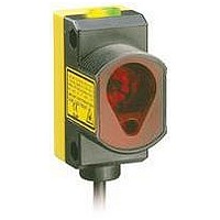
Photoelectric Sensor
Manufacturer
BANNER ENGINEERING
Datasheet
1.QS30ELVC.pdf
(12 pages)
Specifications of QS30ELVC
Output Current
150mA
Sensor Output
NPN/PNP
Supply Voltage Range Dc
10V To 30V
Sensor Housing
Rectangular
Sensing Range Min
100mm
Sensor Input
Optical
Body Material
ABS Plastic
Supply Voltage Max
30VDC


WORLD-BEAM
The switchpoint can be selected during RUN mode and is accomplished via the push
buttons or the remote wire (see Remote Line TEACH, page 7).
Switchpoint selection via push buttons:
• P ress “+” and “-” to select desired switchpoint
• T hree possible choices; 8, 16 or 32 percent below the signal from the retroreflector.
The sensor continues operating normally with the newly selected threshold value. It is not
necessary to repeat the light SET.
In addition to its configuration function, Remote Configuration may be used to disable
the push buttons for security. Disabling the push buttons prevents undesired tampering
with the configuration settings. The Green Power LED blinks 4 times if a push button is
pressed while they are locked out. The sensor continues operating normally and ignores
the button press. Connect the gray wire of the sensor as described on page 2, and four-
pulse to either enable or disable the push buttons:
6
The QS30ELVC Alarm State indicates that the sensor requires attention. In all situations, the alarm can be cleared by realigning the sensor to
the retroreflector, cleaning the sensor or retroreflector of contamination, and performing a Light SET to establish a valid light signal.
Alarm State is indicated by:
• Amber Output LED flashing
• All 3 Red Signal LEDs OFF
• O utput forced to blocked state (i.e. if sensor is in dark operate (DO), the output is conducting)
The sensor may enter Alarm State for three reasons:
In any case, the sensor can be returned to normal operation by ensuring a clean optical path, aligning the sensor to the retroreflector, and
performing a Light SET procedure on the sensor.
Selection does not wrap around.
P/N 139760 rev. A
1. The sensor may be in Alarm State when first powered up. This is normal operation and does not indicate a problem with the sensor.
2. The sensor will enter Alarm State if the Light SET procedure fails. This indicates the sensor did not receive enough light from the
3. The sensor can enter Alarm State if the auto compensation algorithm is enabled and the sensor has automatically adjusted the
The Alarm State will be cleared when a valid Light SET is performed.
retroreflector for reliable detection. Realign the sensor to the retroreflector, making sure all optical surfaces are free of contamination.
threshold as much as possible. The sensor and retroreflector should be cleaned, or the sensor should be realigned to the retroreflector.
The sensor will automatically adapt to the new light level, or a Light SET can be performed to reestablish the light level.
If the automatic compensation algorithm is enabled, the sensor may recover at this point and begin operating normally. It is not
necessary to repeat the Light SET procedure. If automatic compensation has been disabled, the sensor will remain in the Alarm State
until the alignment has been corrected and a Light SET is successfully completed.
®
Switchpoint Selection
Push Button Disable
T
T
T
QS30ELVC Series
T
T T T
T
T
Alarm State
T
T
0.04 < T < 0.8 s
T
T
T
T
T
T
T
T
Banner Engineering Corp. • Minneapolis, MN U.S.A
www.bannerengineering.com • Tel: 763.544.3164
T
T
T
T
T
T
T
T
T
Related parts for QS30ELVC
Image
Part Number
Description
Manufacturer
Datasheet
Request
R

Part Number:
Description:
Photoelectric Sensor
Manufacturer:
BANNER ENGINEERING
Datasheet:

Part Number:
Description:
Photoelectric Sensor
Manufacturer:
BANNER ENGINEERING
Datasheet:

Part Number:
Description:
Photoelectric Sensor
Manufacturer:
BANNER ENGINEERING
Datasheet:

Part Number:
Description:
LEDIR70XD4-XM-81039 MAX INTENS STROBE ONLY NO BANNER MARKS
Manufacturer:
BANNER ENGINEERING
Part Number:
Description:
M18SP6DL-72225 LABELED MOELLER NO BANNER MARKINGS BULK PACK
Manufacturer:
BANNER ENGINEERING
Part Number:
Description:
M18SP6DLQ-72226 LABLED MOELLER NO BANNER MARKINGS BULK PACK
Manufacturer:
BANNER ENGINEERING
Part Number:
Description:
M18SP6L-72223 LABELED MOELLER NO BANNER MARKINGS BULK PACK
Manufacturer:
BANNER ENGINEERING
Part Number:
Description:
Photoelectric Sensor
Manufacturer:
BANNER ENGINEERING
Datasheet:

Part Number:
Description:
Programmable Indicator Light
Manufacturer:
BANNER ENGINEERING
Datasheet:
Part Number:
Description:
INDICATOR LED PANEL 50MM GRN/RED/YEL 30V
Manufacturer:
BANNER ENGINEERING
Datasheet:
Part Number:
Description:
Programmable Indicator Light
Manufacturer:
BANNER ENGINEERING
Datasheet: