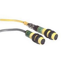
S18AW3R BANNER ENGINEERING, S18AW3R Datasheet - Page 5

S18AW3R
Manufacturer Part Number
S18AW3R
Description
Photoelectric Sensor
Manufacturer
BANNER ENGINEERING
Datasheet
1.S18AW3R.pdf
(7 pages)
Specifications of S18AW3R
Output Current
300mA
Sensing Range Max
20m
Sensor Input
Laser
††
Performance based on use of a model BRT-3 retroreflector (3" diameter).
Actual sensing range may be more or less than specified, depending on the
efficiency and reflective area of the retroreflector used.
Banner Engineering Corp.
www.bannerengineering.com • Tel: 763.544.3164
G
N
E
X
C
E
S
S
G
A
N
E
X
C
E
S
S
G
A
N
E
X
C
E
S
S
G
A
N
E
X
C
E
S
S
A
I
I
I
E
X
C
E
S
S
G
A
N
I
I
1000
1000
1000
1000
1000
100
100
100
100
100
10
10
10
10
(0.033')
(0.033')
10
(0.04")
1
(0.33')
1
0.01 m
1
0.01 m
1
0.1 m
(0.04")
1 mm
1
1 mm
Maximum Gain
Excess Gain
Minimum Gain
Minimum Gain
10 mm
(0.33')
(0.33')
0.1 m
0.1 m
10 mm
(0.4")
(3.3')
(0.4")
with BRT-3 Reflector
with BRT-3 Reflector
1 m
DISTANCE
DISTANCE
DISTANCE
DISTANCE
DISTANCE
S18 Series
S18 Series
S18 Series
S18 Series
S18 Series
Non-Polarized Retro
Polarized Retro
Opposed Mode
Maximum Gain
100 mm
100 mm
Diffuse Mode
Diffuse Mode
(3.3')
(3.3')
Long Range
10 m
(33')
Short Range
1 m
1 m
(4")
(4")
•
Minneapolis, MN U.S.A.
1000 mm
1000 mm
100 m
(330')
10 m
10 m
(40")
(33')
(33')
(40")
1500 mm
1000 mm
1000 mm
1500 mm
120 mm
120 mm
150 mm
100 mm
100 mm
150 mm
15 mm
10 mm
10 mm
15 mm
15 mm
10 mm
10 mm
15 mm
500 mm
500 mm
5 mm
5 mm
80 mm
40 mm
40 mm
80 mm
50 mm
50 mm
5 mm
5 mm
0
0
0
0
0
0
0
0
0
0
S18 Series
Long Range Diffuse
S18 Series
Short Range Diffuse
Polarized Retro
S18 Series
Non-Polarized Retro
S18 Series
S18 Series
Opposed Mode
25 mm
80 mm
Beam Pattern
(3")
0.5 m
(1.6')
0.5 m
(1")
(1.6')
(16')
5 m
with BRT-3 Reflector
with BRT-3 Reflector
160 mm
50 mm
(2")
(6")
1.0 m
(3.2')
1.0 m
(3.2')
DISTANCE
DISTANCE
10 m
(32')
DISTANCE
DISTANCE
DISTANCE
240 mm
75 mm
(9")
1.5 m
(3")
(4.8')
1.5 m
(4.8')
15 m
(49')
Performance Curves
320 mm
100 mm
(12")
2.0 m
2.0 m
(4")
(6.4')
(6.4')
20 m
(66'
)
400 mm
S18 Sensors – ac-Voltage Series
125 mm
(15")
2.5 m
2.5 m
(5")
(8.0')
(8.0')
25 m
(82')
0.6"
0.4"
0.2"
0
0.2"
0.4"
0.6"
0.6"
0.4"
0.2"
0
0.2"
0.4"
0.6"
4.7"
3.2"
1.6"
0
1.6"
3.2"
4.7"
6"
4"
2"
0
2"
4"
6"
60"
40"
20"
0
20"
40"
60"
Focus and spot sizes are typical.
E
X
C
E
S
S
G
A
N
X
C
S
S
G
A
N
I
E
E
E
X
C
E
S
S
G
A
N
I
I
1000
1000
1000
100
Performance based on use of a 90% reflectance white test card.
100
100
10
(0.004")
10
0.1 mm
10
0.1 mm
(0.004")
1
(0.004")
0.1 mm
1
1
(0.04")
(0.04")
1 mm
(0.04")
1 mm
1 mm
DISTANCE
DISTANCE
DISTANCE
S18 Series
S18 Series
S18 Series
Fixed-field mode
Fixed-field mode
with 100 mm far
Fixed-field mode
with 50 mm far
10 mm
with 25 mm far
10 mm
(0.4")
limit cutoff
10 mm
(0.4")
limit cutoff
(0.4")
limit cutoff
Excess Gain
100 mm
100 mm
100 mm
(4")
(4")
(4")
Ø 10 mm spot size @ 8 mm focus
Ø 10 mm spot size @ 25 mm cutoff
†
†
Ø 10 mm spot size @ 10 mm focus
Ø 10 mm spot size @ 50 mm cutoff
†
†
Ø 10 mm spot size @ 20 mm focus
Ø 10 mm spot size @ 100 mm cutoff
†
†
Using 18% gray test card: Cutoff
distance will be 95% of value shown.
Using 6% black test card: Cutoff
distance will be 90% of value shown.
Using 18% gray test card: Cutoff
distance will be 90% of value shown.
Using 6% black test card: Cutoff
distance will be 85% of value shown.
Using 18% gray test card: Cutoff
distance will be 85% of value shown.
Using 6% black test card: Cutoff
distance will be 75% of value shown.
P/N 121521
†
5


