TL-N10ME1 Omron, TL-N10ME1 Datasheet - Page 2
TL-N10ME1
Manufacturer Part Number
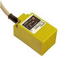
TL-N10ME1
Description
Inductive Proximity Sensor
Manufacturer
Omron
Datasheet
1.TL-N10ME1.pdf
(10 pages)
Specifications of TL-N10ME1
Sensor Input
Inductive
Sensing Range
10mm
Supply Voltage Range Dc
10V To 30V
Sensor Housing
Rectangular
Supply Voltage Max
30VDC
Sensing Range Max
10mm
Switch Terminals
Cable
Output Type
NPN, NO
Maximum Operating Temperature
+ 70 C
Operating Supply Voltage
10 V to 30 V
Sensing Distance
10 mm
Minimum Operating Temperature
- 25 C
Features
NO
Lead Free Status / RoHS Status
Lead free / RoHS Compliant
Available stocks
Company
Part Number
Manufacturer
Quantity
Price
Company:

Part Number:
TL-N10ME1
Manufacturer:
OMRON
Quantity:
1 000
Part Number:
TL-N10ME1
Manufacturer:
OMRON/欧姆龙
Quantity:
20 000
Company:
Part Number:
TL-N10ME1 2M
Manufacturer:
OMRON
Quantity:
500
Company:
Part Number:
TL-N10ME1 5M
Manufacturer:
OMRON
Quantity:
500
Company:
Part Number:
TL-N10ME1 5M
Manufacturer:
OMRON
Quantity:
500
Company:
Part Number:
TL-N10ME1-1 5M
Manufacturer:
OMRON
Quantity:
500


TL-N
J ACCESSORIES
Specifications
J RATINGS/CHARACTERISTICS
TL-NjMD DC 2-wire Models
Note: Response frequencies are average values measured with identical standard sensing objects, on condition that the space between
2
Description
Mounting brackets (supplied with DC sensors; Fits TL-N5 and TL-N7 sensors
Mounting brackets (supplied with DC sensors;
order separately for AC sensors)
Item
Supply voltage (operating voltage range)
Leakage current
Sensing object
Sensing distance
Sensing distance (standard object)
Differential travel
Response frequency (See Note.)
Operating status (with sensing object
approaching)
Control output (switching capacity)
Circuit protection
Indicator
Ambient temperature
Ambient humidity
Temperature influence
Voltage influence
Residual voltage
Insulation resistance
Dielectric strength
Vibration resistance
Shock resistance
Degree of protection
Weight (with 2-m cable)
Material
Material
any adjacent sensing objects was twice the width of a single sensing object and the setting distance was half the maximum sens-
ing distance. Refer to Precautions for details.
Operating
Operating
Case
Sensing surface
TL-N7MDj
12 to 24 VDC (10 to 30 VDC), ripple (p-p): 10% max.
0.8 mA max.
Ferrous metal (Refer to Engineering Data for non-ferrous metal)
7 mm ±10% (0.28 in)
0 to 5.6 mm (0.22 in)
(iron, 30 x 30 x 1 mm)
10% max. of sensing distance
0.5 kHz
D1 models:
D2 models:
3 to 100 mA DC
Load short-circuit protection and surge absorber
D1 models:
D2 models:
- - 25°C to 70°C (- - 13°F to 158°F) with no icing
35% to 95%
±10% max. of sensing distance at 23°C (73.4°F) in the temperature range of
- - 25°C to 70°C (- - 13°F to 158°F)
±2.5% max. of sensing distance within a range of ±15% of the rated power supply
voltage
3.3 V max. with a load current of 100 mA and a cord length of 2 m (78.7 in)
50 MΩ min. (at 500 VDC) between current carry parts and case
1,000 VAC for 1 min between current carry parts and case
10 to 55 Hz, 1.5-mm double amplitude for 2 hours each in X, Y, and Z directions
1,000 m/s
IEC60529 IP67
Approx. 145 g (5.11 oz)
Heat-resistant ABS resin
Heat-resistant ABS resin
Fits TL-N10 and TL-N12 sensors
Fits TL-N20 sensors
2
(3280.8 ft/sec
Load ON
Load OFF
Operation indicator (red LED) and setting indicator (green LED)
Operation indicator (red LED)
2
) approx. 100G for 10 times each in X, Y, and Z directions
TL-N12MDj
12 mm ±10% (0.47 in)
0 to 9.6 mm (0.38 in)
(iron, 40 x 40 x 1 mm)
Approx. 170 g (5.99 oz)
Part number
Y92E-C5
Y92E-C10
Y92E-C20
TL-N20MDj
20 mm ±10% (0.79 in)
0 to 16 mm (0.63 in)
(iron, 50 x 50 x 1 mm)
0.3 kHz
Approx. 240 g (8.46 oz)
TL-N
Related parts for TL-N10ME1
Image
Part Number
Description
Manufacturer
Datasheet
Request
R

Part Number:
Description:
Proximity Sensors TL-W3MB1 W/ ROBOTIC CABLE 2M
Manufacturer:
Omron
Datasheet:

Part Number:
Description:
Proximity Sensors TL-M2ME1 W/ 5 METER CABLE
Manufacturer:
Omron
Datasheet:

Part Number:
Description:
Proximity Sensors MINI FLAT PROX 2MM NPN NO SHLD
Manufacturer:
Omron
Datasheet:
Part Number:
Description:
Proximity Sensors Miniature Inductive 3-Wire DC PNP-NO
Manufacturer:
Omron
Datasheet:
Part Number:
Description:
Proximity Sensors INDUCTIVE NPN-NO
Manufacturer:
Omron
Datasheet:
Part Number:
Description:
Proximity Sensors INDUCTIVE PNP-NO
Manufacturer:
Omron
Datasheet:
Part Number:
Description:
Proximity Sensors MINI FLAT PROX
Manufacturer:
Omron
Datasheet:
Part Number:
Description:
Proximity Sensors INDUCTIVE NPN-NO
Manufacturer:
Omron
Datasheet:

Part Number:
Description:
Inductive Proximity Sensor
Manufacturer:
Omron
Datasheet:

Part Number:
Description:
BLOCK PRX,10MM,NPN,NC,UNSH
Manufacturer:
Omron
Datasheet:
Part Number:
Description:
AC,BLOCK PRX,5MM,NO,UNSH
Manufacturer:
Omron
Datasheet:
Part Number:
Description:
AC,FLAT PRX,2MM,NO,SHLD
Manufacturer:
Omron
Datasheet:
Part Number:
Description:
FLAT PROXIMITY
Manufacturer:
Omron
Datasheet:

Part Number:
Description:
MINI FLAT PROX
Manufacturer:
Omron
Datasheet: