TL-Q5MC1 Omron, TL-Q5MC1 Datasheet - Page 9
TL-Q5MC1
Manufacturer Part Number
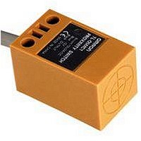
TL-Q5MC1
Description
Inductive Proximity Sensor
Manufacturer
Omron
Datasheet
1.Y92E-C5.pdf
(13 pages)
Specifications of TL-Q5MC1
Sensor Input
Optical
Sensing Range
5mm
Supply Voltage Range Dc
10V To 30V
Sensor Housing
Rectangular
Supply Voltage Max
30VDC
Sensing Range Max
5mm
Contact Current Max
50mA
Output Type
Transistor
Maximum Operating Temperature
+ 70 C
Supply Voltage
24 V
Operating Supply Voltage
10 V to 30 V
Sensing Distance
5 mm
Minimum Operating Temperature
- 25 C
Maximum Output Current
100 mA
Features
NO
Lead Free Status / RoHS Status
Lead free / RoHS Compliant
Available stocks
Company
Part Number
Manufacturer
Quantity
Price
Company:

Part Number:
TL-Q5MC1 10M
Manufacturer:
OMRON
Quantity:
500
Company:
Part Number:
TL-Q5MC1 2M
Manufacturer:
OMRON
Quantity:
500
Company:
Part Number:
TL-Q5MC1 5M
Manufacturer:
OMRON
Quantity:
500
Company:
Part Number:
TL-Q5MC1-3 3M
Manufacturer:
OMRON
Quantity:
500
Company:
Part Number:
TL-Q5MC1-F-Z
Manufacturer:
OMRON
Quantity:
1 000


Safety Precautions
Refer to Warranty and Limitations of Liability.
This product is not designed or rated for ensuring
safety of persons either directly or indirectly.
Do not use it for such purposes.
Do not use this product under ambient conditions that exceed the
ratings.
● Design
Influence of Surrounding Metal
When mounting the Sensor within a metal panel, ensure that the
clearances given in the following table are maintained. Failure to
maintain these distances may cause deterioration in the performance
of the Sensor.
Rectangular Models
Influence of Surrounding Metal
*1. Dimension B is the same value as the value on the sides and the top. (The
*2. The values for A or B for the TL-N apply when there is metal on only one side
Influence of Surrounding Metal
Grooved Model
Influence of Surrounding Metal
• Do not short-circuit the load, otherwise the Sensor may
• Do not supply power to the Sensor with no load,
Model
TL-Q5M@@
TL-N7MD@
TL-N12MD@
TL-N20MD@
TL-N5ME@, TL-N5MY@
TL-N10ME@, TL-N10MY@
TL-N20ME@, TL-N20MY@
Model
TL-Q2MC1
Model
TL-G3D-3
be damaged.
otherwise the Sensor may be damaged.
Applicable Models: AC 2-Wire Models
construction is symmetric around a point.)
of the sensor. If there is metal on two or more sides, the value must be
multiplied by two or more.
3 mm
Precautions for Correct Use
A
TL-Q2MC1
* The mounting plate
must be a non-
ferrous metal.
Mounting plate*
TL-N
A
B
WARNING
*2
*1
A
Distance
Distance
Distance
B
(Unit: mm)
(Unit: mm)
(Unit: mm)
TL-Q
B
B
20
40
50
70
20
40
80
12
11
A
A
A
TL-Q2MC1
B
B *1
A
20
35
40
60
23
30
45
17
*1
B
B
3
Mutual Interference
When installing Sensors face-to-face or side-by-side, ensure that the
minimum distances given in the following table are maintained.
Mutual Interference
* Values in parentheses apply to Sensors operating at different frequencies.
Mutual Interference
Grooved Model
Mutual Interference
Model
TL-Q5MC@
TL-Q5MD@
TL-N7MD@
TL-N12MD@
TL-N20MD@
TL-N5ME@
TL-N5MY@
TL-N10ME@, TL-N10MY@
TL-N20ME@, TL-N20MY@
Model
TL-Q2MC1
Model
TL-G3D-3
Parallel
A
(Unit: mm)
(Unit: mm)
(Unit: mm)
A
Distance
Distance
Distance
A
TL-N/TL-Q/TL-G
Face-to-face
200 (100)
200 (100)
100 (50)
120 (60)
120 (60)
60 (17)
60 (30)
80 (40)
80 (40)
30 (8)
B
A
31
A
A
*
B
B
200 (100)
200 (100)
120 (60)
120 (80)
120 (60)
120 (60)
120 (60)
80 (40)
90 (40)
90 (45)
B
25
B
B
*
9
Related parts for TL-Q5MC1
Image
Part Number
Description
Manufacturer
Datasheet
Request
R

Part Number:
Description:
Proximity Sensors TL-W3MB1 W/ ROBOTIC CABLE 2M
Manufacturer:
Omron
Datasheet:

Part Number:
Description:
Proximity Sensors TL-M2ME1 W/ 5 METER CABLE
Manufacturer:
Omron
Datasheet:

Part Number:
Description:
Proximity Sensors MINI FLAT PROX 2MM NPN NO SHLD
Manufacturer:
Omron
Datasheet:
Part Number:
Description:
Proximity Sensors Miniature Inductive 3-Wire DC PNP-NO
Manufacturer:
Omron
Datasheet:
Part Number:
Description:
Proximity Sensors INDUCTIVE NPN-NO
Manufacturer:
Omron
Datasheet:
Part Number:
Description:
Proximity Sensors INDUCTIVE PNP-NO
Manufacturer:
Omron
Datasheet:
Part Number:
Description:
Proximity Sensors MINI FLAT PROX
Manufacturer:
Omron
Datasheet:
Part Number:
Description:
Proximity Sensors INDUCTIVE NPN-NO
Manufacturer:
Omron
Datasheet:

Part Number:
Description:
Inductive Proximity Sensor
Manufacturer:
Omron
Datasheet:

Part Number:
Description:
BLOCK PRX,10MM,NPN,NC,UNSH
Manufacturer:
Omron
Datasheet:
Part Number:
Description:
AC,BLOCK PRX,5MM,NO,UNSH
Manufacturer:
Omron
Datasheet:
Part Number:
Description:
AC,FLAT PRX,2MM,NO,SHLD
Manufacturer:
Omron
Datasheet:
Part Number:
Description:
FLAT PROXIMITY
Manufacturer:
Omron
Datasheet:

Part Number:
Description:
MINI FLAT PROX
Manufacturer:
Omron
Datasheet: