XS1M30MA230 SQUARE D, XS1M30MA230 Datasheet - Page 90
XS1M30MA230
Manufacturer Part Number
XS1M30MA230
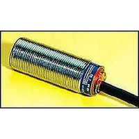
Description
Inductive Proximity Sensor
Manufacturer
SQUARE D
Datasheet
1.XS1M18KP340.pdf
(172 pages)
Specifications of XS1M30MA230
Sensor Input
Inductive
Sensing Range
10mm
Supply Voltage Range Ac
24V To 240V
Sensor Housing
Cylindrical
Sensing Range Max
10mm
Sensor Output
NO
Output Type
NO


Proximity Sensors
XS Tubular Inductive Sensors
Weld Field Immune, DC
Dimensions
286
LED
LED
XS1M12
XS2M12
XS1M18
XS1M30
XS1M12
XS1M18
a = Overall Length (mm)
b = Threaded Section (mm)
c = for Non-shielded Sensors (mm)
a
2.3" (60)
2.3" (60)
2.3" (60)
2.3" (60)
a
b
b
1.6" (40)
1.5" (38)
1.6" (40)
1.6" (40)
LED
LED
XS1M30
XS2M12
c
0
0.16" (4)
0
0
c
XS Tubular Inductive Sensors / Weld Field Immune, DC
Features
Industrial welding processes create fields of electromagnetic “noise” which can interfere with
the magnetic fields of inductive proximity sensors. Standard proximity sensors can be falsely
triggered when near to these fields. WFI sensors allow uninterrupted performance when
placed extremely close to the conductor carrying the welding current.
• The body styles are cylindrical in 0.47", 0.7" and 1.18" (12, 18 and 30 mm) diameters.
• Enclosure material is brass coated in Teflon
• Available in Micro connector versions.
• Mounting nuts included.
a
The formula below shows the relationship between distance (r [mm]) and electromagnetic flux
density (B[MT]).
Circuit
Type
12 mm Shielded, DC with Micro Connector a, Nominal Sensing Distance–2 mm
PNP
12 mm Non-shielded, DC with Micro Connector a, Nominal Sensing Distance–4 mm
PNP
18 mm Shielded, DC with Micro Connector a, Nominal Sensing Distance–5 mm
PNP
30 mm Shielded, DC with Micro Connector a, Nominal Sensing Distance–10 mm
PNP
B [mT] = 0.2xI [A] B [mT] =
XS1M12
XS2M12
XS1M18
XS1M30
Minimum Mounting Clearances
Side by side
sticking to sensing face, reducing the possibility of false triggering.
See p. 518 for matching connector cables.
Output
Mode
N.O.
N.O.
N.O.
N.O.
e
Side by Side
e
IN
0.59
r [mm]
0
0
0
©1997
Voltage
Range
10 to 36 Vdc
10 to 36 Vdc
10 to 36 Vdc
10 to 36 Vdc
-
2002 Schneider Electric All Rights Reserved
mm
15
0
0
0
r [mm] =
I[A] =
Face to face
Face to Face
e
IN
0.27
0.27
0.63
0.79
Voltage Drop
Maximum
2.5 V
2.5 V
2.5 V
2.5 V
Electromagnetic Flux Density
Welding Current
Distance
mm
16
20
e
7
7
a
Load Current
Maximum
250 mA
250 mA
250 mA
250 mA
Facing a Metal Object
e
IN
0.24
0.43
0.35
0.79
®
to prevent slag (molten bits of metal) from
Facing a metal object
mm
11
20
6
9
Operating Frequency
Maximum
1000 Hz
1000 Hz
500 Hz
250 Hz
e
Mounted in Metal
d
IN
1.42
1.18
0.47
0.71
Mounting in a metal support
mm
12
36
18
30
H
Catalog
Number
XS1M12PAW01D
XS2M12PAW01D
XS1M18PAW01D
XS1M30PAW01D
h
IN
0.31
0
0
0
D
mm
0
8
0
0
10/02
Related parts for XS1M30MA230
Image
Part Number
Description
Manufacturer
Datasheet
Request
R


Part Number:
Description:
Pushbutton, Non-Illum'd Red "STOP", Momentary, 1NO-1NC, Square 30mm, 10A, 600V
Manufacturer:
SQUARE D
Datasheet:

Part Number:
Description:
KITS,TWIDO? PROGRAMMABLE CONTROLLERS,KITS,TWIDOPACK STARTER KIT - ADVANCED LEVEL,PROGRAMMABLE CONTROLLERS,TWIDO? PROGRAMMABLE CONTROLLERS ,SQUARE D
Manufacturer:
SQUARE D

Part Number:
Description:
LAMPS,INDICATOR,STACKABLE,LAMPS, STACKABLE INDICATOR,VISUAL INDICATING SIGNALS,XVB SERIES INDICATING BANKS ,SQUARE D
Manufacturer:
SQUARE D
Part Number:
Description:
LAMPS,INDICATOR,STACKABLE,LAMPS, STACKABLE INDICATOR,VISUAL INDICATING SIGNALS,XVB SERIES INDICATING BANKS ,SQUARE D
Manufacturer:
SQUARE D
Datasheet:
Part Number:
Description:
I/O EXTENDER MODULE 4 D IN & 2 D OUTPUT
Manufacturer:
SQUARE D
Datasheet:
Part Number:
Description:
CB ACCESSORY, UNDERVOLTAGE TRIP 48V DC
Manufacturer:
SQUARE D
Datasheet: