TL-W5MD1 Omron, TL-W5MD1 Datasheet
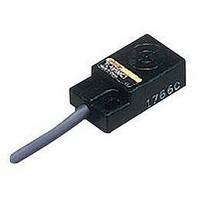
TL-W5MD1
Specifications of TL-W5MD1
Available stocks


Related parts for TL-W5MD1


TL-W5MD1 Summary of contents
Page 1
... Sensing distance 1 Unshielded Shielded 5 mm *1. Models with a different frequency are also available to prevent mutual interference. The model numbers are TL-W@M@@5 (e.g., TL-W5MD15). *2. Models with robotics cables are also available. The model numbers are TL-W@MC1-R (e.g., TL-W1R5MC1-R). Model Operation mode NO NC TL-W5MD1 *1 TL-W5MD2 *1 ...
Page 2
... The response frequency is an average value. Measurement conditions are as follows: standard sensing object, a distance of twice the standard sensing object, and a set distance of half the sensing distance. TL-W5MD@ Refer to the timing charts under I/O Circuit Diagrams on page 6 for details times each and Z directions TL-W 2 ...
Page 3
... C2/B2 Models: NC ±2.5% max. of sens- ing distance at rated voltage in the rated voltage ±20% range 3 times each and Z directions Approx Instruction manual TL-W TL-W5E1, TL-W5E2 TL-W20ME1 TL-W5F1, TL-W5F2 TL-W20ME2 20 mm ±10 15% of sensing distance Iron, 50 × 50 × 300 Hz min min VDC ( VDC ( VDC VDC), ripple ripple (p-p): 20% max ...
Page 4
... Sensing head TL-W5E/-W5F −10 −8 −6 −4 − Distance Y (mm) Sensing head TL-W3MC1 −6 −4 − Distance Y (mm) Sensing head TL-W20 −20 −15 −10 − Distance Y (mm) Sensing head TL-W TL-W5MC1/-W5MD −8 −6 −4 − Distance Y (mm) Sensing head 4 ...
Page 5
... Iron Stainless steel (SUS304) 2 Brass Aluminum Copper Side length of sensing object: d (mm) TL-W20 × Iron Stainless steel (SUS304 Brass 6 Aluminum Side length of sensing object: d (mm) TL-W TL-W5MC1 7 d × Iron Stainless steel 4 (SUS304) 3 Brass Aluminum 2 Copper Side length of sensing object: d (mm) 5 ...
Page 6
... I/O Circuit Diagrams DC 2-Wire Models Operation mode Model Non-sensing area Sensing object (%) NO TL-W5MD1 Sensing object (%) NC TL-W5MD2 DC 3-Wire Models Operation mode Model TL-W1R5MC1 NO TL-W3MC1 TL-W5MC1 TL-W3MC2 NC TL-W5MC2 TL-W5E1 NO TL-W20ME1 TL-W5E2 NC TL-W20ME2 NO TL-W5F1 NC TL-W5F2 Timing chart Set position Unstable Stable sensing sensing area ...
Page 7
... TL-W5MD@ TL-W5MC1@ TL-W20ME@ n TL-W5E@/-W5F@ l Proximity Note: Values in parentheses apply to Sensors operating at different Sensor frequencies. ● Mounting • Use M3 flat-head screws to mount the TL-W1R5MC1 and TL- W3MC1 • Do not exceed the torque in the following table when tightening the 8 resin cover screws Model 20 ...
Page 8
... Indicator *2 10 *1. TL-W5MC1 4-dia. vinyl-insulated round cable with 3 conductors (Conductor cross section: 0.2 mm Insulator diameter: 1.2 mm), Standard length TL-W5MD@ 4-dia. vinyl-insulated round cable with 2 conductors (Conductor cross section: 0.3 mm Insulation diameter: 1.3 mm), Standard length *2. C Models: Detection indicator (red) ...
Page 9
... Please read and understand this catalog before purchasing the products. Please consult your OMRON representative if you have any questions or comments. WARRANTY OMRON's exclusive warranty is that the products are free from defects in materials and workmanship for a period of one year (or other period if specified) from date of sale by OMRON. OMRON MAKES NO WARRANTY OR REPRESENTATION, EXPRESS OR IMPLIED, REGARDING NON-INFRINGEMENT, MERCHANTABILITY, OR FITNESS FOR PARTICULAR PURPOSE OF THE PRODUCTS ...