E2CCR8A Omron, E2CCR8A Datasheet - Page 4
E2CCR8A
Manufacturer Part Number
E2CCR8A
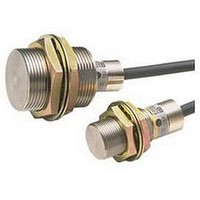
Description
Inductive Proximity Sensor
Manufacturer
Omron
Series
E2Cr
Datasheet
1.E2C-GE4A.pdf
(23 pages)
Specifications of E2CCR8A
Sensor Input
Inductive
Sensing Range
1.8mm
Switch Terminals
Cable
Sensing Face Diameter
3.5mm
Sensor Output
NPN, NO/NC
Peak Reflow Compatible (260 C)
No
Sensor Housing
Rectangular
Lead Free Status / RoHS Status
Contains lead / RoHS non-compliant


Amplifier Units
Item
Power supply volt-
age (operating volt-
age range)
Current
consumption
Sensing distance
adjustment range *2
Differential travel
adjustment range
Re-
sponse
time
Control
outputs
Indicators
Operation mode
Self-diagnostic
output
Timer function
Cable length
compensation
between Sensor and
Amplifier Unit
Ambient
temperature range
Ambient
humidity range
Temperature
influence
Voltage influence
Insulation
resistance
Dielectric strength
Vibration resistance Destruction: 10 to 25 Hz, 2-mm double ampli-
Solid-
state
Relay
Solid-
state
Relay
Model
12 to 24 VDC (10 to 30 VDC), ripple (p-p): 10% max. *1
25 mA max.
20% min. of rated sensing distance with 4-
turn potentiometer
Differential travel fixed (10% max. of sensing distance)
(Refer to the response frequency of the Proximity Sensor.)
NPN
Load resistance: 4.7
kΩ,
100 mA max.
(40 VDC max.)
(Residual voltage:
1.5 V max.)
Detection indicator (red)
(OPERATION)
Changed with NO/NC switch.
Operating/storage: −10 to 55°C (with no icing or condensation)
Operating/Storage: 35% to 85% (E2C-JC4AP: 35% to 95%) (with no condensation)
10% max. of sensing distance at 23°C in the temperature range of −10 to 55°C
DC Models: ±1% max. of sensing distance at rated voltage in the rated voltage ±20% range
AC Models: ±1% max. of sensing distance at rated voltage in the rated voltage ±10% range
50 MΩ min. (at 500 VDC) between current-carrying parts and case
DC Models: 1,000 VAC, 50/60 Hz for 1 min between current-carrying parts and case
AC Models: 1,500 VAC, 50/60 Hz for 1 min between current-carrying parts and case
tude for 2 hours each in X, Y, and Z directions
E2C-GE4A
---
---
---
PNP
Load resistance: 4.7
kΩ,
100 mA max.
(40 VDC max.)
(Residual voltage:
1.5 V max.)
E2C-GF4A
45 mA max.
20% to 100% of rated sensing distance with 4-turn potentiometer
NPN
Open-collector output
100 mA max.
(40 VDC max.)
(Residual voltage:
0.7 V max.)
(E2C-JC4AP: 1 V
max.)
Detection indicator
(red) (OPERATION)
Stability indicator
(green) (STABILITY)
(E2C-JC4AP only)
Output transistor
turns ON when Sen-
sor open circuit or un-
stable sensing is
detected; solid-state
NPN
open-collector
50 mA max.
(40 VDC max.)
(Residual voltage:
1 V max.)
OFF-delay: 40
±10 ms
(E2C-JC4AP only)
3 m/5 m, terminals
Short-plate switching
Shorted: 1 to 3 m
Open: 3 to 5 m
Destruction: 10 to
55 Hz,
1.5-mm double ampli-
tude for 2 hours each
in X, Y, and Z direc-
tions
E2C-JC4AP
E2C-JC4A
---
---
25 mA max.
NPN/PNP output
Open-collector output
200 mA max.
(40 VDC max.)
(Residual voltage: 1.5 V max.)
Detection indicator
(red) (OPERATION)
Switched between 3
and 5 m.
Destruction: 10 to 25 Hz, 2-mm double amplitude for 2 hours each in
X, Y, and Z directions
E2C-WH4A
50 mA max.
1% to 5% of rated sensing distance
Detection indicator (red) (OPERATION)
Stability indicator (green) (STABILITY)
Mode switched with 4-position switch.
E2C-AM4A
---
---
E2C/E2C-H
100 to 240 VAC
(90 to 264 VAC)
50/60 Hz
55 mA max.
20 ms max.
Transistor/photocou-
pler
50 mA max.
(40 VDC max.)
(Residual voltage:
2 V max.)
Relay output, SPDT
2 A at 250 VAC, cosφ
= 1
(resistive load) *3
E2C-AK4A
4
Related parts for E2CCR8A
Image
Part Number
Description
Manufacturer
Datasheet
Request
R

Part Number:
Description:
G6S-2GLow Signal Relay
Manufacturer:
Omron Corporation
Datasheet:
Part Number:
Description:
Compact, Low-cost, SSR Switching 5 to 20 A
Manufacturer:
Omron Corporation
Datasheet:
Part Number:
Description:
Manufacturer:
Omron Corporation
Datasheet:
Part Number:
Description:
Manufacturer:
Omron Corporation
Datasheet:
Part Number:
Description:
Manufacturer:
Omron Corporation
Datasheet:
Part Number:
Description:
Manufacturer:
Omron Corporation
Datasheet:
Part Number:
Description:
Manufacturer:
Omron Corporation
Datasheet:
Part Number:
Description:
Manufacturer:
Omron Corporation
Datasheet: