GX-3SB PANASONIC EW, GX-3SB Datasheet - Page 6
GX-3SB
Manufacturer Part Number
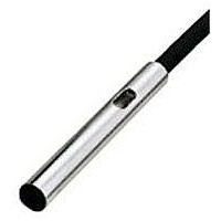
GX-3SB
Description
Inductive Proximity Sensor
Manufacturer
PANASONIC EW
Datasheet
1.GX-3SB.pdf
(10 pages)
Specifications of GX-3SB
Sensor Input
Inductive
Sensing Range
0.8mm
Supply Voltage Range Dc
12V To 24V
Lead Free Status / RoHS Status
Lead free / RoHS Compliant


I/O CIRCUIT AND WIRING DIAGRAMS
I/O circuit diagram
I/O circuit diagram
Note: GX-3S , GX-4S
Internal circuit
If a capacitor of 1 !F or more is connected between 0 V and output or
between
below.
Symbols ... D : Reverse supply polarity protection diode
Symbols ... D : Reverse supply polarity protection diode
GX-5S
GX-8ML
GX-3S
GX-4S
protection at the output. Do not connect them directly to a power
supply or a capacitive load.
T
Internal circuit
Internal circuit
r
Z
D
Tr
Z
Tr : NPN output transistor
V and output, connect a 100
Z
Tr : NPN output transistor
D
D
GX-8M
GX-5M
D
D
: Surge absorption zener diode
: Surge absorption zener diode
(Brown)
(Black) Output
(Blue) 0 V
Z
D
Users’ circuit
100
200 mA max. (Note)
(Brown)
(Black) Output (Note)
(Blue) 0 V
(Brown)
(Black) Output
(Blue) 0 V
and GX-5M
V
Users’ circuit
Users’ circuit
Color code
Color code
1 !F or more
1 !F or more
50 mA max.
V
V
Signal
0 V
V
Load
Load
do not incorporate a short-circuit
Without the resistor, the short-
circuit protection is activated by
the charge or discharge current
of the capacitor, so that it results
in delaying the response
whenever the sensor switches.
The connected resistor solves
this problem.
resistor in series as shown
10 to 30 V DC
12 to 24 V DC
10 %
Wiring diagram
Wiring diagram
Note: The maximum sink current varies depending on the ambient
200
100
temperature.
0
25
13
Ambient temperature ( C F)
Brown
Black
Blue
Brown
Black
Blue
Load
131
Load
55
158
70
10 to 30 V DC
GX
12 to 24 V DC
10 %
749
Related parts for GX-3SB
Image
Part Number
Description
Manufacturer
Datasheet
Request
R

Part Number:
Description:
3.8MM SHIELDED NPN APPR ON (NO) 0.8MM 1KHZ IP67 X-FLEX CABLE 5M
Manufacturer:
PANASONIC EW

Part Number:
Description:
Inductive Proximity Sensor
Manufacturer:
PANASONIC EW
Datasheet:

Part Number:
Description:
M12 NON-SHIELD DC 2WIRE APPR ON (NO) 3MM 1.2KZ IP67G
Manufacturer:
PANASONIC EW
Part Number:
Description:
M12 NON-SHLD DC 2WIRE APPR ON (NO) 3MM 1.2KHZ IP67G QD
Manufacturer:
PANASONIC EW
Part Number:
Description:
M12 SHIELD DC 2 WIRE APP ON(NO) 3MM 1.2KHZ IP67 QD
Manufacturer:
PANASONIC EW
Part Number:
Description:
M12 SHIELD DC 2WIRE LEAVE ON (NC) 3MM 1.2KHZ IP67Z
Manufacturer:
PANASONIC EW
Part Number:
Description:
M12 SHIELD DC 2WIRE LEAVE ON (NC) 3MM 1.2KHZ IP67G
Manufacturer:
PANASONIC EW
Part Number:
Description:
M18 NON-SHIELD DC 2WIRE APPR ON (NO) 7MM 500HZ IP67G
Manufacturer:
PANASONIC EW
Part Number:
Description:
M18 NON-SHLD DC 2 WIRE APPR ON (NO) 7MM 500HZ IP67G QD
Manufacturer:
PANASONIC EW
Part Number:
Description:
M18 NON-SHIELD DC 2WIRE LEAVE ON (NC) 7MM 500HZ IP67G
Manufacturer:
PANASONIC EW

Part Number:
Description:
SIGNAL RELAY, DPDT, 5VDC, 2A, PC BOARD
Manufacturer:
PANASONIC EW
Datasheet:


Part Number:
Description:
PHOTOMOS RELAY, 60VDC, 400mA
Manufacturer:
PANASONIC EW
Datasheet:

Part Number:
Description:
PHOTOMOS RELAY, 400V, 150mA
Manufacturer:
PANASONIC EW
Datasheet: