UB2000-30GM-E5-V15 PEPPERL & FUCHS, UB2000-30GM-E5-V15 Datasheet - Page 2
UB2000-30GM-E5-V15
Manufacturer Part Number
UB2000-30GM-E5-V15
Description
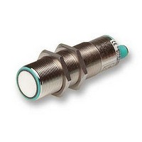
PROXIMITY SWITCH
Manufacturer
PEPPERL & FUCHS
Type
Ultrasonicr
Datasheets
1.UB2000-30GM-E5-V15.pdf
(2 pages)
2.UC2000-30GM-IUR2-V15.pdf
(5 pages)
3.UB2000-30GM-E5-V15.pdf
(3 pages)
Specifications of UB2000-30GM-E5-V15
Frequency Response Max
3.3Hz
Sensing Range Max
2000mm
Sensor Input
Ultrasonic
Supply Voltage Dc Max
30V
Contact Current Max
200mA
External Length / Height
109mm
Ip/nema Rating
IP65
Body Style
Cylindrical
Current, Switching
200 mA
Function
Proximity
Ip Rating
IP65
Output
PNP
Primary Type
Proximity
Range, Measurement
2 m
Technology
Ultrasonic
Termination
Quick Disconnect
Voltage, Supply
30 VDC
Input Voltage
10-30 VDC (15-30 VDC for Analog Voltage Output)
Operating Temperature
–14°F to +158°F
Sensing Face
Epoxy Resin/Silica Composite
Housing Material
Nickel-Plated Brass (UB), Stainless Steel (UC)
Sensor Protection
Short-Circuit, Overload, Reverse Polarity
Sealing
IP 65
Standard Target
100 mm × 100 mm Flat Plate
Connection Type
V15
Operating Temperature Max
70°C
Operating Temperature Min
-25°C
Output Type
PNP
Response Time
480ms
Sensing Range
80mm To 2000mm
Frequency
180kHz
Beam Divergence
60°
Operating Temperature Range
-25°C To +70°C
Length/height, External
109mm
Rohs Compliant
Yes


Subject to reasonable modifications due to technical advances.
Pepperl+Fuchs Group • Tel.: Germany (06 21) 7 76-0 • USA (330) 4 25 35 55 • Singapore 7 79 90 91 • Internet http://www.pepperl-fuchs.com
Function
Window mode,
close function
Window mode,
open function
1 switching point,
close function
1 switching point,
open function
Detection of
object presence
Displays in dependence on operat-
ing mode
Teach switching point
Object detected
No object detected
Object uncertain (TEACH-IN invalid)
Normal operation
Interference (e.g. compressed air)
Hinweise
Note
Function
Synchronisation
The sensor features a synchronisation input for the suppression of mutual interfer-
ence. It can be synchronised by applying a square wave voltage. The falling edge
of a synchronisation pulse at the synchronisation input starts a measuring cycle. A
low level > 1 s or an open synchronisation input will result in the non-synchronised
normal operation of the sensor. A high level at the synchronisation input disables
the sensor. Synchronisation cannot be performed during TEACH-IN and vice versa.
Two operating modes are possible:
1. Multiple sensors can be controlled by the same synchronisation signal. The sen-
2. The synchronisation pulses are sent cyclically to individual sensors. The sensors
Setting the switching points
The ultrasonic sensor features a switch output with two teachable switching points.
These are set by applying the supply voltage -UB or +UB to the TEACH-IN input.
The supply voltage must be applied to the TEACH-IN input for at least 1 s. LEDs
indicate whether the sensor has recognised the target during the TEACH-IN proce-
dure. Switching point A1 is taught with -UB, A2 with +UB.
Five different output functions can be set:
Default setting of switching points: A1 = blind range, A2 = nominal distance
sors are synchronised.
operate in multiplex mode.
TEACH-IN procedure
- Set object to near switching point
- Teach switching point A1 with -UB
- Set object to far switching point
- Teach switching point A2 with +UB
- Set object to near switching point
- Teach switching point A2 with +UB
- Set object to far switching point
- Teach switching point A1 with -UB
- Set object to near switching point
- Teach switching point A2 with +UB
- Cover sensor or remove all objects from sensing range
- Teach switching point A1 with -UB
- Set object to near switching point
- Teach switching point A1 with -UB
- Cover sensor or remove all objects from sensing range
- Teach switching point A2 with +UB
- Cover sensor or remove all objects from sensing range
- Teach switching point A1 with -UB
- Teach switching point A2 with +UB
Green LED
Flashing
Flashing
On
Off
Off
Red LED
Flashing
Flashing
Off
Off
Off
Switching state
Previous state
Yellow LED
Off
On
Off
Copyright Pepperl+Fuchs, Printed in Germany
Model number
UB2000-30GM-E2-V15
Characteristic curves/
Additional information
LED-Window
Programmed switching output function
Characteristic response curves
Window operation, normally open function
A1 < A2:
Window operation, normally closed function
A2 < A1:
One switch point, normally open function
A1 ->
One switch point, normally closed function
A2 ->
A1 -> , A2 -> : Detection of presence of object
Object detected: Switch output closed
No object detected: Switch output open
0.0
0.5
1.0
1.5
90 80
Curve 1: flat plate 100 mm x 100 mm
Curve 2: round bar, Ø 25 mm
Distance [m]
70
60
"Power on"/Disturbance
A1
A2
A2
A1
50
2.0
Dual-LED
green/red
40
2
2.5
A2
A1
3.0
30
object range
1
Switch output
LED
yellow
Angle [degrees]
3.5
-20
20
-10
10
0
2
Related parts for UB2000-30GM-E5-V15
Image
Part Number
Description
Manufacturer
Datasheet
Request
R


Part Number:
Description:
WE77/EX-1 230V, PEPPERL + FUCHS, SWITCH ISOLATOR 230V
Manufacturer:
PEPPERL & FUCHS
Datasheet:
Part Number:
Description:
Rotary Encoders - Absolute
Manufacturer:
PEPPERL & FUCHS


Part Number:
Description:
LED Pilot Light
Manufacturer:
PEPPERL & FUCHS
Datasheet:

Part Number:
Description:
LED Pilot Light
Manufacturer:
PEPPERL & FUCHS
Datasheet:
Part Number:
Description:
LED Pilot Light
Manufacturer:
PEPPERL & FUCHS
Datasheet:
Part Number:
Description:
LED Pilot Light
Manufacturer:
PEPPERL & FUCHS
Datasheet: