E3G-MR19G Omron, E3G-MR19G Datasheet - Page 11
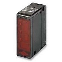
E3G-MR19G
Manufacturer Part Number
E3G-MR19G
Description
PHOTOSWITCH, POL REFLEX
Manufacturer
Omron
Datasheet
1.E3G-MR19G.pdf
(14 pages)
Specifications of E3G-MR19G
Svhc
No SVHC (15-Dec-2010)
Sensing Range Max
10m
Sensor Input
Optical
Supply Voltage Ac Max
240VAC
Supply Voltage Dc Max
24VDC
Contact Voltage Ac Max
250VAC
Contact Voltage Dc Max
30VDC
Dielectric
RoHS Compliant
Output Type
Relay
Response Time
30ms
Rohs Compliant
Yes
Dielectric Strength Vdc
2000VAC
External Depth
68mm
External Length / Height
84.95mm
External Width
29mm


(Recommended example)
• Changing to Side-pullout Cable from Vertical-pullout Cable
E3G
Pro-
dure
ce-
A
B
C
D
(4)
Remove the present cover.
Attach the E39-L129-G Terminal Protection Cover for
side-pullout cable.
Remove the clamping nut, washer, and rubber bushing
of the E3G. These are used for the side-pullout cable.
Attach the rubber bushing and cap provided with the
E39-L129-G to the E3G as replacements.
33mm
63mm
Rubber bushing *
Cap *
(4)
(5)
Power supply
(1)
(2)
(1) Tc
(2) Ta
(3) Tb
(3)
Output
Operation
Note: * Provided with the E39-L129-G
(2)
Rubber bushing
Washer
E39-L129-G Terminal
Protection Cover
Rubber bushing
Washer
Clamping nut
Clamping nut
Terminal
protection cover
Design
Load Relay Contact
If a load is used that will spark when it is turned OFF (e.g. a
contactor or valve), the usually closed side may be turned ON
before the usually open side is turned OFF or vice versa. If
both usually open output and usually closed output are used
simultaneously, apply an surge suppressor to the load. (Refer
to OMRON's "Switch/Relay/Connector (PCB Product) Cata-
log" for typical examples of surge suppressors.
Wiring Considerations
Connection/Wiring
The E3G has load short-circuit protection. If load short-circuit
or like has occurred, the output turns OFF. Therefore, recheck
the wiring and switch power on again. This resets the short-
circuit protection circuit. Load short-circuit protection is acti-
vated when a current of 2 times or more of the rated load cur-
rent flows. When using an L load, use the one the inrush
current of which is less than 1.2 times of the rated load cur-
rent.
Mounting
• If Sensors are mounted face-to-face, ensure that no optical
• Be sure to install the Sensor carefully so that the directional
• Do not strike the Photoelectric Sensor with a hammer or any
• Use M4 screws for Sensor installation.
• For case installation, tighten it to the torque of 1.2 Nm max.
Water Resistance
Tighten the operation cover screws and terminal block cover
screws to a torque of 0.3 to 0.5 Nm in order to ensure water
resistivity.
axes cross each other. Otherwise, mutual interference may
result.
angle range of the Sensor will not be directly exposed to in-
tensive light, such as sunlight, fluorescent light, or incan-
descent light.
other tool during the installation of the Sensor, or the Sensor
will loose its water-resistive properties.
All E3G Models
A-129
Related parts for E3G-MR19G
Image
Part Number
Description
Manufacturer
Datasheet
Request
R

Part Number:
Description:
Photoelectric Sensors - Industrial NPN/PNP POL RETRORFL
Manufacturer:
Omron
Datasheet:
Part Number:
Description:
Photoelectric Sensors - Industrial NPN/PNP DIFF REFLECT
Manufacturer:
Omron
Datasheet:

Part Number:
Description:
CONVERGENT 50mm PNP CONN.
Manufacturer:
Omron
Datasheet:
Part Number:
Description:
CONVERGENT 50mm NPN CABLE
Manufacturer:
Omron
Datasheet:

Part Number:
Description:
CONVERGENT 50mm PNP CABLE
Manufacturer:
Omron
Datasheet:
Part Number:
Description:
CONVERGENT 50mm NPN CONN.
Manufacturer:
Omron
Datasheet:
Part Number:
Description:
CONVERGENT 200mm PNP CABLE
Manufacturer:
Omron
Datasheet:
Part Number:
Description:
CONVRGNT.2M AC/DC TMR SCR.TERM
Manufacturer:
Omron
Datasheet:

Part Number:
Description:
PHOTOSWITCH, POL REFLEX, TIMED
Manufacturer:
Omron
Datasheet:

Part Number:
Description:
G6S-2GLow Signal Relay
Manufacturer:
Omron Corporation
Datasheet:
Part Number:
Description:
Compact, Low-cost, SSR Switching 5 to 20 A
Manufacturer:
Omron Corporation
Datasheet:
Part Number:
Description:
Manufacturer:
Omron Corporation
Datasheet: