E3Z-LS81 Omron, E3Z-LS81 Datasheet - Page 7
E3Z-LS81
Manufacturer Part Number
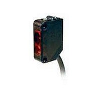
E3Z-LS81
Description
BGS/FGS SENSOR,PNP 2M CABLE
Manufacturer
Omron
Type
Photoelectric Sensorsr
Series
E3Zr
Specifications of E3Z-LS81
Rohs Compliant
YES
Features
Adjustable sensing distance
Light Source
Red LED
Sensing Distance
0.787" ~ 7.874" (20mm ~ 200mm) ADJ
Sensing Method
Reflective, Diffuse
Sensing Object
White Paper
Output Configuration
PNP - Dark-ON/Light-ON - Selectable
Sensing Light
Red
Mounting Type
Bracket Mount
Current - Supply
30mA
Voltage - Supply
12 V ~ 24 V
Package / Case
Module, Pre-Wired
Lead Free Status / RoHS Status
Lead free / RoHS Compliant
Lead Free Status / RoHS Status
Lead free / RoHS Compliant
Available stocks
Company
Part Number
Manufacturer
Quantity
Price
Company:

Part Number:
E3Z-LS81
Manufacturer:
OMRON
Quantity:
1 000
Company:
Part Number:
E3Z-LS81
Manufacturer:
OMRON
Quantity:
374


PNP Output
Plugs (Sensor I/O Connectors)
Nomenclature
E3Z-LS81
E3Z-LS86
E3Z-LS83
E3Z-LS88
E3Z-LS81
E3Z-LS86
Stability indicator (green)
3
Model
4
Set distance adjuster
(5-turn endless adjustment)
2
1
1
2
3
4
Operation
Light-ON
Dark-ON
Light-ON
Dark-ON
mode
XS3F-M421-402-A
XS3F-M421-405-A
XS3F-M422-402-A
XS3F-M422-405-A
Operation
indicator
(orange)
Output
transistor
Load
(e.g., relay)
Operation
indicator
(orange)
Output
transistor
Load
(e.g., relay)
Operation
indicator
(orange)
Output
transistor
Load
(e.g., relay)
Operation
indicator
(orange)
Output
transistor
Load
(e.g., relay)
Timing charts
OFF
OFF
OFF
(Between blue and black leads)
OFF
OFF
OFF
(Between blue and black leads)
OFF
OFF
OFF
(Between blue and black leads)
(Between blue and black leads)
ON
ON
ON
OFF
OFF
OFF
ON
ON
ON
ON
ON
ON
ON
ON
ON
Wire color
NEAR
NEAR
NEAR
NEAR
Brown
White
Blue
Black
FAR VERY FAR
FAR VERY FAR
Operation indicator (orange)
Operation selector
FAR
FAR
E39-ECON@M
E39-ECONW@M
(DARK ON)
(DARK ON)
Operation
selector
(LIGHT
(LIGHT
D side
D side
L side
L side
ON)
ON)
BGS:
Either leave
the pink
wire (2)
open or
connect it to
the blue
wire (3).
FGS:
Connect
the pink
wire (2) to
the brown
wire (1).
BGS/FGS
selection
method
Operation
indicator
(orange)
Classifi-
cation
DC
Stability
indicator
(green)
Brown
White
color
Black
Wire
Blue
Connector Pin Arrangement
Photo-
electric
Sensor
Main
Circuit
Output circuit
Connector
(Control output)
pin No.
1
2
1
2
3
4
4
3
Z
D
1
4
2
3
Power supply (0 V)
Power supply (+V)
Brown
Black
Pink
Blue
BGS/FGS selec-
Application
E3Z-LS
Output
100 mA
max.
tion
FGS
BGS
12 to 24 VDC
Load (relay)
0 V
7
Related parts for E3Z-LS81
Image
Part Number
Description
Manufacturer
Datasheet
Request
R

Part Number:
Description:
EMITTER ONLY FOR E3Z-T61
Manufacturer:
Omron
Datasheet:

Part Number:
Description:
Sensor; NPN/PNP; Photoelectric; 100 mm to 4 m; Red; 12 to 24 VDC 10 %; ABS
Manufacturer:
Omron Automation
Datasheet:
Part Number:
Description:
Sensor; PNP; Polarized Retroreflective Sensing Mode; Photoelectric; 30 mA; 1 ms
Manufacturer:
Omron Automation
Datasheet:

Part Number:
Description:
Photoelectric Sensors - Industrial Emitter Only for E3Z -T81
Manufacturer:
Omron
Datasheet:
Part Number:
Description:
LaserType TB,emit Only M12 NPN
Manufacturer:
Omron
Datasheet:
Part Number:
Description:
Thru Beam Sensor
Manufacturer:
Omron
Datasheet:
Part Number:
Description:
Cable
Manufacturer:
Omron
Datasheet:

Part Number:
Description:
1 AXIS NPN PRE-WIRED
Manufacturer:
Omron
Datasheet:

Part Number:
Description:
BGS/FGS SENSOR,PNP M8 CONECTR
Manufacturer:
Omron
Datasheet:
Part Number:
Description:
G6S-2GLow Signal Relay
Manufacturer:
Omron Corporation
Datasheet:
Part Number:
Description:
Compact, Low-cost, SSR Switching 5 to 20 A
Manufacturer:
Omron Corporation
Datasheet:
Part Number:
Description:
Manufacturer:
Omron Corporation
Datasheet: