8655MHRA0901LF FCI, 8655MHRA0901LF Datasheet - Page 15
8655MHRA0901LF
Manufacturer Part Number
8655MHRA0901LF
Description
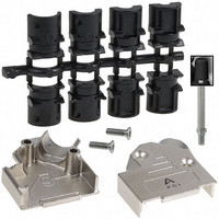
BACKSHELL DB9 45DEG METAL SHLD
Manufacturer
FCI
Specifications of 8655MHRA0901LF
Accessory Type
Two Piece Backshell
Number Of Positions
9
Cable Type
Round
Cable Exit
45°
Shielding
Shielded
Plating
Nickel
Hardware
Assembly Hardware, Strain Relief
Features
Mating Screws 4-40
Color
Silver
Product
Standard Hoods & Connectors
Number Of Positions / Contacts
9
Gender
Female
Mounting Style
Cable
Mounting Angle
Straight
Termination Style
Screw
Housing Material
Zinc Alloy with Nickel Plating
Operating Temperature Range
- 40 C to + 120 C
Accessory
D-Sub Metal Shells
Connector Type
Hood
Number Of Rows
2
D Sub Shell Size
DE
Connector Body Material
Zinc Alloy
Cable Exit Angle
45°
Connector Shell Size
DE
Enclosure Material
Zinc Alloy
Rohs Compliant
Yes
For Use With
DEMF09SN - DSUB DM SIG STB 9 SOCKETDEM09SN - DSUB DM SIG STB 9 SOCKETDEM09PN - DEM09PN DSUB DM SIG STB 9 PINDE09P065HTXLF - DSUB SIGNAL STC 9PINDE09S065HTLF - DSUB SIGNAL STC 9SOCKETDE09P064HTXLF - DSUB SIGNAL STC 9PINDEML09P - DSUB DM SIG STB 9 PINDEMF09S - DSUB DM SIG STB 9 SOCKETDE09S064HTLF - DSUB SIGNAL STC 9SOCKET8656V09PLTXLF - DSUB CRIMP 9 PIN609-2810 - CONN DSUB PLUG 15POS SOLDER CUP609-1467 - CONN DSUB FEMALE 9POS CRIMP GOLD609-1466 - CONN DSUB MALE 9POS CRIMP GOLD
Lead Free Status / RoHS Status
Lead free / RoHS Compliant
Other names
609-1458
Available stocks
Company
Part Number
Manufacturer
Quantity
Price
Company:

Part Number:
8655MHRA0901LF
Manufacturer:
FCI
Quantity:
70


DELTA D - Straight solder to board
SPECIFIC DIMENSIONS
15
25
37
50
9
P
S
P
S
P
S
P
S
P
S
30.81
30.81
39.14
39.14
53.03
53.03
69.32
69.32
67.10
67.10
A
±0.38
B
24.99
24.99
33.32
33.32
47.04
47.04
63.50
63.50
61.11
61.11
±0.12
C
16.96
16.96
25.18
25.18
39.12
39.12
55.68
55.68
54.11
54.11
±0.10
5.90
5.90
G
6.05
6.05
5.70
6.05
5.70
6.05
5.70
6.05
±0.25
-0
+0.15
–0
+0.15
–0
–
–
5.60
5.60
5.60
5.60
5.60
5.60
5.60
5.60
5.60
5.60
14
Terminal
M
6.00
6.00
6.00
6.00
6.00
6.00
6.00
6.00
6.00
6.00
24
±0.10
6.90
6.90
6.90
6.90
6.90
6.90
6.90
6.90
6.90
6.90
34
14 A
24 A
34 A
2.90
2.90
2.90
2.90
2.90
2.90
2.90
2.90
2.90
2.90
Terminal length
N
±0.30
3.70
3.70
3.70
3.70
3.70
3.70
3.70
3.70
3.70
3.70
24 B
15
Related parts for 8655MHRA0901LF
Image
Part Number
Description
Manufacturer
Datasheet
Request
R

Part Number:
Description:
(FCI-HR005 - FCI-HR040) Large Active Area and High Speed Silicon Photodiodes
Manufacturer:
Laser Components
Datasheet:
Part Number:
Description:
(FCI-INGAAS-55 - FCI-INGAAS-500) High Speed InGaAs Photodiodes
Manufacturer:
Laser Components
Datasheet:
Part Number:
Description:
Door, lock & key
Manufacturer:
GAMEWELL-FCI [Gamewell-FCI by Honeywell]
Datasheet:
Part Number:
Description:
30485Fire Fighter Phone Accessories
Manufacturer:
GAMEWELL-FCI Gamewell-FCI by Honeywell
Datasheet:

Part Number:
Description:
Manufacturer:
FCI
Datasheet:
Part Number:
Description:
Manufacturer:
FCI
Datasheet: