XF2L-0735-1 Omron, XF2L-0735-1 Datasheet - Page 24
XF2L-0735-1
Manufacturer Part Number
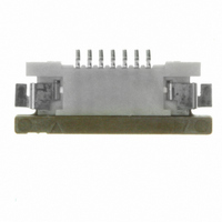
XF2L-0735-1
Description
CONN FPC 7POS 0.5MM SMT
Manufacturer
Omron
Series
XF2Lr
Type
FPC Connectorr
Datasheet
1.XF2L-0725-1.pdf
(28 pages)
Specifications of XF2L-0735-1
Contact Plating
Gold Over Nickel
Connector Type
Bottom Contacts
Number Of Positions
7
Pitch
0.020" (0.50mm)
Ffc, Fcb Thickness
0.30mm
Height Above Board
0.047" (1.20mm)
Mounting Type
Surface Mount, Right Angle
Cable End Type
Straight
Termination
Solder
Locking Feature
Slide Lock
Features
Zero Insertion Force (ZIF)
Contact Finish
Tin Alloy
Contact Finish Thickness
79µin (2.00µm)
Operating Temperature
-30°C ~ 85°C
Current Rating
0.500A
Voltage Rating
50V
Housing Material
Liquid Crystal Polymer (LCP)
Contact Gender
SKT
Mounting Style
Surface Mount
Number Of Contact Rows
1
Number Of Contacts
7POS
Pitch (mm)
0.5mm
Body Orientation
Right Angle
Contact Resistance Max
30mOhm
Voltage Rating Max
50VDC/50VAC
Operating Temp Range
-30C to 85C
Current Rating (max)
0.5A
Housing Color
Natural
Contact Material
Copper Alloy
Termination Method
Solder
Product Height (mm)
1.2mm
Product Depth (mm)
3.45mm
Product Length (mm)
8.4mm
Gender
Receptacle
Pitch Spacing
0.5mm
No. Of Contacts
7
No. Of Rows
1
Ffc/fpc Thickness
0.3mm
Contact Termination
Surface Mount Vertical
Product Type
PCB
Number Of Positions / Contacts
7
Mounting Angle
Vertical
Termination Style
Solder
Lead Free Status / RoHS Status
Contains lead / RoHS non-compliant
Lead Free Status / RoHS Status
Contains lead / RoHS non-compliant, Contains lead / RoHS non-compliant
Other names
OR679TR
XF2L07351
XF2L07351
Available stocks
Company
Part Number
Manufacturer
Quantity
Price
Company:

Part Number:
XF2L-0735-1A
Manufacturer:
OMRON
Quantity:
33 362
Company:
Part Number:
XF2L-0735-1Z
Manufacturer:
OMRON
Quantity:
3 000


24
XF
4. When unlocking the slider (lever), place your fingers on
5. When inserting and removing the FPC, be sure to check
Using the FPC in the follow ways may damage the FPC,
either side or the entire slider (lever) and slowly lift the
slider (lever) up and away.
Do not engage the slider (lever) past its initial location
during the unlocking process. Doing so may result in
damage to the connector or contact failure.
Performing the following action may cause the terminals
to change shape or otherwise cause contact failures.
that the slider (lever) has been unlocked first.
change the shape of the contacts, or result in contact fail-
ure.
• Using tweezers to unlock the slider (lever).
• Removing the FPC when the slider (lever) is still locked.
Primary location
6. Make sure that the FPC has been inserted correctly and
Mounting
1. Do not perform reflow or manual soldering with the FPC
2. The reflow conditions are as stated in OMRON’s specifi-
Designing
1. Gently pull out the FPC taking care not to apply force
2. When installing the FPC at a location or on equipment
3. Use the FPCs that conform to the appropriate specifica-
4. Use the same metal for the FPC plating and the connec-
5. “Whiskers” may protrude from the FOC film of some lead-
6. When designing the board, be sure to allow locking and
7. Make sure that the metal mask thickness is within the
not backward.
aligned with the customer's design specification may
damage the contacts and equipment may malfunction.
inserted in the connector and the slider (lever) in the
locked position. Doing so may result in contact failure.
cations and guidelines. These conditions, however,
depend on the type of solder, the manufacturer, the
amount of solder, the size of the circuit board, and the
other mounting materials. Confirm the mounting condi-
tions before proceeding.
directly to the connector. Bending the FPC in the area
where it enters the connector or applying force to the FPC
itself may result in contact failure.
that will subject the FPC to repeated vibration or move-
ment, secure the FPC prior to use.
tions and size as stated by OMRON. When using a differ-
ent FPC, or an F/F, contact OMRON.
tor plating.
free FPCs. Be careful when using these units.
operating space for the slider (lever).
appropriate specifications and size as stated by OMRON.
The recommended metal mask open area is 90% of the
printed circuit board mating dimensions given in the
dimensions diagrams.
• Removing the FPC by pulling it up and down or from left
Inserting the FPC incorrectly with the connecting face not
to right or twisting it sideways.
Component
XF
Related parts for XF2L-0735-1
Image
Part Number
Description
Manufacturer
Datasheet
Request
R

Part Number:
Description:
CONN FPC 26POS 0.5MM SMT
Manufacturer:
Omron
Datasheet:

Part Number:
Description:
FPC CONNECTOR
Manufacturer:
Omron
Datasheet:

Part Number:
Description:
CONN FPC 4POS 0.5MM PITCH SMD
Manufacturer:
Omron
Datasheet:

Part Number:
Description:
CONN FPC 8POS 0.5MM PITCH SMD
Manufacturer:
Omron
Datasheet:

Part Number:
Description:
CONN FPC 12POS 0.5MM PITCH SMD
Manufacturer:
Omron
Datasheet:

Part Number:
Description:
G6S-2GLow Signal Relay
Manufacturer:
Omron Corporation
Datasheet:
Part Number:
Description:
Compact, Low-cost, SSR Switching 5 to 20 A
Manufacturer:
Omron Corporation
Datasheet:
Part Number:
Description:
Manufacturer:
Omron Corporation
Datasheet:
Part Number:
Description:
Manufacturer:
Omron Corporation
Datasheet:
Part Number:
Description:
Manufacturer:
Omron Corporation
Datasheet:
Part Number:
Description:
Manufacturer:
Omron Corporation
Datasheet: