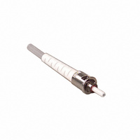
6100-W 3M, 6100-W Datasheet

6100-W
Specifications of 6100-W
54007911418
6100
6100W
80-6107-4702-6
80-6111-2753-3
80610747026
80611127533
MF6100
Available stocks
Related parts for 6100-W
6100-W Summary of contents
Page 1
SC, FC and ST Fiber Optic Connectors Instructions September 1998 78-8073-7873-8 Hot Melt * ...
Page 2
2 ...
Page 3
Contents 1.0 Safety and Helpful Hints ........................................................................................................................................................4 2.0 Field Termination Kit Contents ..............................................................................................................................................4 3.0 STÑInstallation on 900 µm Buffered Fiber ..........................................................................................................................6 4.0 STÑInstallation on Jacketed Cable........................................................................................................................................8 5.0 SCÑInstallation on 900 µm Buffered Fiber ........................................................................................................................10 6.0 SCÑInstallation on Jacketed Cable ....................................................................................................................................12 ...
Page 4
... Isopropyl alcohol is not shipped with the 3M Field Termination Kits; however, a bottle for the alcohol is included. Note: Carefully follow safety, health and environmental information given on the container label or the Material Safety Data Sheet for the isopropyl alcohol being used ...
Page 5
Crimp Tool 2.13 6955-S Fiber Buffer and Coating Stripper 2.16 Lint-Free Cloths 2.11 Jacket Removal Tool 2.14 Scribe 2.17 Alcohol and Water Bottles (Shipped Empty) 5 2.12 Scissors 2.15 View Scope ...
Page 6
STÑInstallation on 900 µm Buffered Fiber 3.1 Turn on the Hot Melt Oven. The oven requires 5 minutes to warm up. 3.4 Load the connector onto the ST * connector holder. 3.7 Place the strain relief boot and clear ...
Page 7
Clean the fiber with a lint free cloth moistened with isopropyl alcohol. 3.13 Push the buffered fiber until it stops. 3.16 Place the buffered fiber in the cable holder. 3.11 Remove the connector holder from the oven. CAUTION: VERY ...
Page 8
STÑInstallation on Jacketed Cable 4.1 Turn on the Hot Melt Oven. The oven requires 5 minutes to warm up. 4.4 Load the connector onto the ST * connector holder. 4.7 Place the strain relief boot on the cable. 4.10 ...
Page 9
Min. (16 mm) 1/8" (1-3 mm) 4.13 Stripping template. 4.16 Remove the connector holder from the oven. CAUTION: VERY HOT. 4.19 Bare fiber should be visible in the bottom of the connector holder. ...
Page 10
SCÑInstallation on 900 µm Buffered Fiber 5.1 Turn on the Hot Melt oven. The oven requires 5 minutes to warm up. 5.4 Load the connector into the SC connector holder. 5.7 Place the strain relief boot, clear strain relief ...
Page 11
Clean the fiber with a lint free cloth moistened with isopropyl alcohol. 5.13 Push the buffered fiber until it stops. 5.16 Verify that the bare fiber is visible in the bottom of the connector holder. 5.19 Place the connector ...
Page 12
SCÑInstallation on Jacketed Cable 6.1 Turn on the Hot Melt oven. The oven requires 5 minutes to warm up. 6.4 Load the connector into the SC connector holder. 6.7 Place the strain relief boot and crimp ring on the ...
Page 13
Min. (14 mm) (14-16 mm) 6.13 Stripping template. 6.16 Remove the connector holder from the oven. CAUTION: VERY HOT. 6.19 Slide the crimp ring over the aramid yarn until it is seated ...
Page 14
FCÑInstallation on 900 µm Buffered Fiber 7.1 Turn on the Hot Melt oven. The oven requires 5 minutes to warm up. 7.4 Load the connector into the FC connector holder. Align the key on the connector with the key ...
Page 15
Remove the connector holder from the oven. CAUTION: VERY HOT. 7.13 Slide the crimp ring over the backbone until it is against the connector. 7.16 Crimp the larger part of the crimp ring with the .190 cavity of the ...
Page 16
FCÑInstallation on Jacketed Cable 8.1 Turn on the Hot Melt oven. The oven requires 5 minutes to warm up. 8.4 Load the connector into the FC connector holder. Align the key on the connector with the key way on ...
Page 17
Clean the fiber with a lint free cloth moistened with isopropyl alcohol. 8.16 Gently insert the fiber into the connector. 8.19 Verify that the bare fiber is visible in the bottom of the connector holder. 8.22 Place the connector ...
Page 18
Scribing 9.1 Remove the connector from the connector holder. 9.3 Pull the fiber away from the connector. Pull along the axis of the fiber, not to one side or the other. If the fiber does not break away, score ...
Page 19
Multimode Polishing Procedure This procedure is for multimode connectors and single-mode connectors that require only a -27 dB reflection. For single-mode applications that require better reflection performance, follow the procedure in Section 11. 10.1 Perform an air polish on ...
Page 20
Place the jig on the lapping film. 10.14 Clean the connector end face with a lint free cloth moistened with isopropyl alcohol. 10.17 Good polish (single-mode) 10.20 Too much pressure when scribing. 10.11 Place the ferrule in the jig ...
Page 21
FC ConnectorÑInstall the boot on the connector. 10.26 Install the shell by aligning the chamfers in the shell with the chamfers on the connector. 11.0 Single-Mode Polishing Procedure 11.1 Perform an air polish on the fiber by gently moving ...
Page 22
Place the connector ferrule in the polishing jig to verify that it fits properly. The fit should allow for easy movement of the ferrule. 11.10 Place the jig on the lapping film. 11.13 Beginning with a light pressure, move ...
Page 23
Add several drops of distilled water to the lapping film. 11.22 Hold the connector as shown. 11.25 Inspect the connector end face with the view scope. Section 10 has pictures of properly and improperly polished connectors. 11.20 Place the ...
Page 24
... Crimp Ring Description Qty Packaging 6300 SC Hot Melt MM, white boot 60 6300-R SC Hot Melt MM, red boot 60 6300-B SC Hot Melt MM, black boot 60 6100 ST Hot Melt MM, white boot 60 6100-R ST Hot Melt MM,red boot 60 6100 ST Hot Melt MM, black boot 60 Buffer Boot for SC and FC, white 60 Crimp Ring, 2 ...


