BRT-THG-2-100 BANNER ENGINEERING, BRT-THG-2-100 Datasheet - Page 5
BRT-THG-2-100
Manufacturer Part Number
BRT-THG-2-100
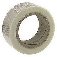
Description
TAPE, RETRO REFLECTIVE, 50MMX2.5M
Manufacturer
BANNER ENGINEERING
Specifications of BRT-THG-2-100
Roll Length
2.5m
Tape Type
Reflective
Width
50mm
Length
2.5 m
Reflectivity Factor
0.7
Standards
CE Marked
Temperature, Operating, Maximum
60°C
For Use With
Photoelectric Sensors
Lead Free Status / Rohs Status
RoHS Exempt Product


Banner Engineering Corp. • Minneapolis, MN U.S.A. • bannerengineering.com • Tel: 763.544.3164
System Power Requirements
Short Circuit Protection
Response Time
Safety Rating
EDM Input
System Reset Input
USSI 1 Reset Input
USSI 1 Input
USSI 2 Input
OSSD Outputs
Non-Safety Outputs
(Aux., Weak Signal, Fault)
Remote Status Interface
Controls and Adjustments
Ambient Light Immunity
Strobe Light Immunity
Emitter Element
Enclosure Rating
Connections
Operating Conditions
Status Indicators
24V dc +15%, 10% maximum ripple; 500 mA max., exclusive of output load
All inputs and outputs are protected from short circuits to +24V dc or dc common
Optical Channel: 13 milliseconds max. (Time between the interruption of an optical path and the
OSSD safety outputs turning off.)
USSI Inputs: 7 milliseconds max. (Time between actuation of the safety stop input device and the
OSSD safety outputs turning off.)
Type 4 per IEC 61496-1, -2; Category 4 per ISO 13849-1 (EN 954-1)
Two normally closed contact inputs for external device monitoring (EDM). Each input monitors the
status of a forced-guided monitor contact of an external safety device or MPCE. The EDM inputs
must be high (10 to 30V dc) when the external device or MPCE is OFF, and must be low (less than 3V
dc) when the external device or MPCE is ON. External devices or MPCEs must meet certain timing
requirements, depending on the configuration setting
The Reset input must be high (10 to 30V dc) for 0.25 to 2 seconds and then low (less than 3V dc) to
reset the system from a manual power-up, optical channel latch or system lockout condition.
The Reset input must be high (10 to 30V dc) for 0.25 to 2 seconds and then low (less than 3V dc) to
reset the system from a manual power-up, optical channel latch or system lockout condition.
Dual-channel, redundant inputs for monitoring output contacts or handshake compatible safety solid-
state outputs of other safety stop devices. OFF (stop) signals cause the PICO-GUARD OSSDs to latch
OFF (Latch condition).
Dual-channel, redundant inputs for monitoring output contacts or handshake-compatible safety solid-
state outputs of other safety stop devices. OFF (stop) signals cause the PICO-GUARD OSSDs to turn
OFF (Trip condition).
Two diverse-redundant solid state 24V dc, 0.5A max. sourcing OSSD (Output Signal Switching
Device) safety outputs.
Solid state 24V dc (> Vin – 1.5V dc), 0.25A max. sourcing non-safety outputs
Isolated RS-232 non-safety output for setup or monitoring the system status. Connections provided
for a Remote Display unit (see Accessories on page 52).
Redundant switches for Auto/Manual power-up, Trip/Latch output operation and 1- or 2-channel EDM
operation. Redundant switches for ON/OFF of each optical channel. (NOTE: At least one optical
channel must be ON.)
> 10,000 lux at 5° angle of incidence
Totally immune to one Federal Signal Corp. "Fireball" model FB2PST strobe
Visible red LED, 660 nm at peak emission
IEC IP20, NEMA 1
See pages 300-302 for general hookup information.
Temperature: 0° to 50° C (+32° to 122° F)
Relative Humidity: 95% maximum (non-condensing)
System Status (bi-color Red/Green): overall status of the PICO-GUARD system
System Reset (bi-color Yellow/Red): status of the System Reset input; indicates system reset needed
Channel (4 bi-color Red/Green): each shows the status of one optical channel
USSI (2 bi-color Red/Green): status of the USSI input channels (a-b and c-d)
USSI 1 Reset (bi-color Yellow/Red): status of USSI 1 reset input; indicates USSI 1 reset needed
EDM (bi-color Red/Green): status of the EDM input channels
OSSD (bi-color Red/Green): status of the OSSD outputs
Config (bi-color Red/Green): status of the system configuration
PICO-GUARD Controller Specifications
ON-state voltage: > Vin-1.5V dc
OFF-state voltage: 1.2V dc max.
Max. load resistance: 1,000 ohms
Max. load capacitance: 0.1 µF
PICO-GUARD
™
Systems
Controller
47