CCM04-1889LFT R102 C&K Components, CCM04-1889LFT R102 Datasheet
CCM04-1889LFT R102
Specifications of CCM04-1889LFT R102
CCM04-1889 LFT
CCM04-1889LFT
Y1142-1889A LFT


Related parts for CCM04-1889LFT R102


CCM04-1889LFT R102 Summary of contents
Page 1
... Variety of heights - Optional card detection switches - Packaged in tape and reel CCM01 MKII CCM02 MKII CCM03 MKII with Auto Lock Cover CCM04 MKII CCM04 MKIII with switch 4 CCM03 MKIII CCM04 MKIII CCM04 MKII Dimensions are shown in mm Specifications and dimensions subject to change ...
Page 2
... Smart Card Interconnect Selector Guide and Index CCM01 CCM02 CCM02 CCM03 CCM03 CCM03 CCM04 Designed for ISO Card • • • (85 mm) Designed for Micro Card ( mm) Blade switch versions Sealed switch versions • • • Fixed contacts • Landing contacts • ...
Page 3
CCM01 MK II The CCM01 MK II connectors with fixed contacts have been developed for applications where a landing contact mechanism is not required but performance and reliability are still key considerations. Features • Available with 8 contacts which are ...
Page 4
Dimensional Drawings 55,6 ±0,2 0,65 54,3 1 Snap 19,12 3x 2,54 Feet 52 A Designation & Date-Code area 2x 0,7 0 CCM01- 2065 0,3 A PCB Layout (Component side) Plastic outline Contact ...
Page 5
CCM02 MK I CCM02 connector with landing contacts. Features • Available with 8 through hole contacts. • 100,000 card insertion cycles. • The contacts do not touch the card until it is almost fully inserted - ...
Page 6
Dimensional Drawings 0,6 x 0,3 ø0,3A B 18,68 7,62 7,62 5,08 51,5 2 REF 55,55 B PCB Layout (Component Side 5,08 7,62 7,62 18,68 51,5 (3x2,54) CCM02-1NO-32 5,8 3,1 4,3 +0,1 0 ø 3,1 0 -0,05 Marking ...
Page 7
CCM02 MK II The CCM02 MK II connectors with landing contacts are dedicated for applications where the reader usage is high and the life span of the card is a key consideration. A connector with contacts which land on the ...
Page 8
Dimensional Drawings 55,6 ±0,2 0,65 54,3 1,8 19,12 4 Snap Feet 52 A Designation & Date-Code area "CCM02" marking is optional A CCM02- XXXX A 10x 1 0,3 A PCB Layout (Component side) Plastic outline Contact foot area 0,8 x ...
Page 9
CCM03 new range of CCM03 connectors have been developed to interface with SIM/SAM cards as defined by GSM11- 11 and ENV1375-1. The connectors are available with either hinged covers or fixed covers and have been designed to ...
Page 10
Ordering Code Part Number Number of Contacts CCM03-3001 R102 6 CCM03-3002 R102 6 CCM03-3003 R102 8 CCM03-3004 R102 8 CCM03-3009 R102 6 CCM03-3010 R102 6 CCM03-3011 R102 8 CCM03-3012 R102 8 CCM03-3013 R102 6 CCM03-3514 R102 6 CCM03-3504 R122 8 ...
Page 11
CCM03 MK II Hinged Cover Insulated Card Presence Switch Dimensional Drawings 25,5 ±0,2 2,1 0,7 25˚0' SEE DETAIL A 29,65 5,65 ±0,2 3,5 2,45 Slider locked Pick and place area ø 3,5 3,81 3,8 R 1,9 Note: Coplanarity of soldering ...
Page 12
Dimensional Drawings Hinged Cover CCM03 - 3514 (6 contacts - with switch on metal lock) 25,5 ±0,2 Right lock switch terminal 2,1 13,15 Left lock switch terminal 0,7 25˚0' SEE DETAIL A 29,65 5,65 ±0,2 13,8 3,5 2,45 R 1,9 ...
Page 13
CCM03 MK II Fixed Cover Dimensional Drawings 30˚0' Pick and place area ø3,5 A XX-XXX Date Code area PCB Layout CCM03 - 3505 (Component side) 1,5 Plastic outline Contact foot area 0 5,5 Pad Prohibited ...
Page 14
A new range of CCM03 connectors have been developed to interface with SIM/SAM cards as defined by GSM11- 11 and ENV1375-1. The connectors are available with a hinged metallic cover and have been designed to provide an easier open/lock function ...
Page 15
CCM03 MK II with Auto Lock cover Dimensional Drawings 24,6±0,2 12,05 5 4,9 DETAIL A 29,6 Pick and place area Date Code area ø3,2 xx-xxx 2 11,61 0,25 29,1 Note: Coplanarity of soldering surfaces: ± 0,05 mm PCB Layout (Component ...
Page 16
Dimensional Drawings Hinged Cover CCM03 - 3518 (6 contacts and switch) 24,6±0,2 5,1 11,8 11,8 0,5 UNLOCKED LOCKED SEE DETAIL A 29,65 Pick and place area Date Code area ø3,2 4,4 3,2 4,4 0,95 Note: Coplanarity of soldering surfaces: ± ...
Page 17
CCM03 MK III The CCM03 Series SIM/SAM Card Connector features an integrated card detection switch. This connector provides a competitive advantage to smart card reader device manufacturers by minimizing the space usage on the PCB, and features a side entry ...
Page 18
Dimensional Drawings A-A Mated condition 3,81 3,81 14,25 ±0,2 11,8 5,9 2,4 2,4 Pick and place area ø3,5 A XX-XXX 4,9 Date Code area 15,1 PCB Layout (Component side) Plastic outline Contact foot area 1,5 0,8 x 0,7 Pad 0,075 ...
Page 19
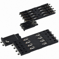
... The CCM04 low profile without card guidance is dedicated to applications where the overall height of the connector is paramount. A range of low profile CCM04 connectors are available with 1.25 mm thick moldings. The wide choice of contact confi ...
Page 20
... CCM04-1814 contacts Mated condition SEE DETAIL A 3,81 3,81 30˚0' 25,5 ±0,2 Date Code area XX-XXX Pick and place area ø3,5 CCM04-1889 contacts + switch Mated condition 30˚0' 3,81 3,81 10,9 SEE DETAIL B 25,5 ±0,2 23,6 Pick and place area ø 3,5 XX-XXX ...
Page 21
... CCM04 MK III Miniature Connectors Introducing a new range of CCM04 connectors designed to interface with either full or SIM/SAM smart cards and designed to minimize space usage on the PCB . Features • Available with contacts. • The contact area is spooned to reduce the risk of accidental (or deliberate) damage and to optimize the electrical connection with the card. • ...
Page 22
... Plastic outline Contact foot area DETAIL A Contact location according to ISO 7816-2 & ENV 1375-1 & GSM11-11 0,8 14,25 (REF.) Unless otherwise stated, tolerances are ± 0, CCM04 MK III Dimension Dimension A B 8,15 10,45 12,85 15,15 8,35 10,65 11,95 14,25 ...
Page 23
... CCM04 MK III 8 Contacts Versions Part Number Total Total Height Length CCM04-5123 1,90 11,8 CCM04-5129 1,90 14,3 CCM04-5113 2,10 11,8 CCM04-5130 2,10 14,3 CCM04-5131 2,40 14,3 CCM04-5125 2,50 11,8 CCM04-5132 2,65 14,3 CCM04-5127 2,80 11 contacts SMT IN - Dimensional Drawings 11,8 Mated condition SEE DETAIL A ...
Page 24
... With tape and reel packaging as standard, the connectors are designed to be automatically pick and placed. EMV trademark owned by EMVCoLLC. CCM04 MK III with switch Construction Insulator Contacts Contact finish PC Tail plating Mechanical Data Mechanical life ...
Page 25
... CCM04 MK III with switch contacts SMT OUT - Dimensional Drawings A-A Mated condition 3,81 SEE DETAIL A 14,25 ±0,2 11,8 Date Code area XX-XXX A Pick and place area ø3,3 5,9 PCB Layout (Component side) 1,5 11, Pad 3,81 3,81 Contact foot area 14,25 0,8 x 0,7 ...