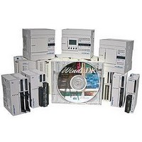
FC4A-T08K1 IDEC, FC4A-T08K1 Datasheet - Page 19

FC4A-T08K1
Manufacturer Part Number
FC4A-T08K1
Description
Expansion Module
Manufacturer
IDEC
Datasheet
1.FC4A-M08BR1.pdf
(24 pages)
Specifications of FC4A-T08K1
Ip/nema Rating
IP20
Supply Voltage
24V
No. Of Digital Outputs
8
Output Type
Transistor
No. Of Channels
8
Rohs Compliant
Yes
For Use With
MicroSmart Programmable Logic Controller Output Expansion Modules, Transistor (Sink/Source) I/O Points 8-output
Lead Free Status / RoHS Status
Lead free / RoHS Compliant
Analog Input Specifications
www.idec.com
Input Signal Type
Input Range
Input Impedance
Allowable Conductor Resistance
Input Detection Current
Sample Duration Time
Sample Repetition Time
Total Input System Transfer Time
Type of Input
Operating Mode
Conversion Method
Input Error
Data
Noise
Resistance
Dielectric Strength
Type of Protection
Effect of Improper Input Connection
Maximum Permanent Allowed
Overload (No damage)
Selection of Analog Input Signal Type
Calibration or Verification to Maintain
Rated Accuracy
NOTES FOR ANALOG EXPANSION UNITS:
1. * Total input system transfer time = Sample repetition time x 2 + 1 scan time
2. ** The 12-bit data (0 to 4095) processed in the analog I/O module can be linear-converted to a value between -32768 and 32767. Select the
3. # When an error is detected, a corresponding error code is sorted to a data register allocated to analog I/O operating status.
optional range designations and analog I/O data minimum and maximum values by using data registers allocated to analog I/O modules.
Maximum Error at 25°C
Temperature Coefficient
Repeatability after
Stabilization Time
Non-lineality
Maximum Error
Digital Resolution
Input Value of LSB
Data Type in Application
Program
Monotonicity
Input Data Out of Range
Maximum Temporary
Deviation during
Electrical Noise Tests
Common Mode
Characteristics
Common Mode Voltage
Input Filter
Cable
Crosstalk
Programmable Logic Controllers
USA: (800) 262-IDEC or (408) 747-0550, Canada: (888) 317-IDEC
Analog Input Specifications (Expansion Modules)
±3% maximum when a 500V clamp voltage is applied to the power and I/O wiring
Twisted pair shielded cable recommended for
Single-ended input
Voltage Input
1 M minimum
0 to 10V DC
13V DC
2.5 mV
—
—
FC4A-L03A1, FC4A-J2A1
improved noise immunity
32 msec + 1 scan time *
16 msec maximum
16 msec maximum
±0.2% of full scale
0 to 4095 (12-bit data); -32768 to 32767 (optional range designation) **
Current Input
4 to 20 mA DC
40 mA DC
Photocoupler between input and internal circuit
10
4 µA
—
—
Common mode reject ratio (CMRR): -50 dB
500V between input and power circuit
Using software programming
Impossible (approx. 10 years)
4096 increments (12 bits)
±0.006% of full scale / °C
±0.5% of full scale
±0.2% of full scale
±1% of full scale
2 LSB maximum
K: 0.325°C; J: 0.300°C; T: 0.100°C
Detectable #
tion accuracy (±4°C maximum)
No damage
reference junction compensa-
Self scan
16V DC
type ADC
±0.2% of full scale plus
Yes
No
Type K (0 to 1300°C)
Type J (0 to 1200°C)
Type T (0 to 400°C)
Thermocouple
1 M minimum
Differential input
—
—
100 msec + 1 scan time *
50 msec maximum
50 msec maximum
FC4A-L03AP1
—
—
Accuracy is not assured when
Resistance Thermometer
MicroSmart Series
±0.2% of full scale
Pt 100 3-wire type
1.0 mA maximum
noise is applied
1 M minimum
200 maximum
(-100 to 500°C)
0.15°C
J-23
J


