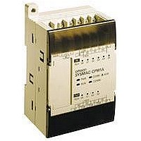
CPM1A-20CDR-A-V1 Omron, CPM1A-20CDR-A-V1 Datasheet - Page 13

CPM1A-20CDR-A-V1
Manufacturer Part Number
CPM1A-20CDR-A-V1
Description
Micro Programmable Logic Controller
Manufacturer
Omron
Specifications of CPM1A-20CDR-A-V1
Output Type
Relay
External Width
86mm
Supply Voltage Max
240VAC
External Depth
70mm
Mounting Type
DIN Rail
External Height
90mm
Supply Voltage Min
100VAC
Approval Bodies
UL, CSA, CE
Rohs Compliant
Yes
Lead Free Status / RoHS Status
Lead free / RoHS Compliant
I/O Specifications
Input Circuit
CPU
Note: 1.
Expansion I/O Unit
Note: The actual ON/OFF delay includes an input constant of 1, 2, 4, 8, 16, 32, 64, or 128 ms (default: 8 ms).
Output Circuit
CPU and Expansion I/O Unit
Relay Output
52
Item
Input voltage
Input impedance
Input current (typical)
ON voltage
OFF voltage
ON delay (see note 1)
OFF delay (see note 1)
Item
Input voltage
Input impedance
Input current (typical)
ON voltage
OFF voltage
ON delay (see note 1)
OFF delay (see note 1)
Item
Maximum switching capacity 250 V AC/2 A (cos =1)
Minimum switching capacity 5 V DC, 10 mA
Relay
service
life
ON delay
OFF delay
2.
3.
Elec-
trical
Mechanical
The actual ON/OFF delay includes a digital filter with a time constant of 1, 2, 4, 8, 16, 32, 64, or 128 ms (default: 8 ms).
The delays for IN00000 to IN00002 are as follows when used for the high-speed counter.
The delays for IN00003 to IN00006 are as follows when used for the high-speed counter.
*1
Input
IN00000 (A-phase)
IN00001 (B-phase)
IN00002 (Z-phase)
Delay
For detailed specifications of expansion I/O units, see page 68.
Resistive
load
Inductive
load
Specifications
24 V DC +10%/–15%
IN00000 to IN00002: 2 k
Others: 4.7 k
IN00000 to IN00002: 12 mA
Others: 5 mA
14.4 V DC min.
5.0 V DC max.
1 to 128 ms max. (default: 8 ms) (see note 1)
1 to 128 ms max. (default: 8 ms) (see note 1)
Specifications
24 V DC +10%/–15%
4.7 k
5 mA
14.4 V DC min.
5.0 V DC max.
1 to 128 ms max. (default: 8 ms) (see note 1)
1 to 128 ms max. (default: 8 ms) (see note 1)
Specifications
24 V DC/2 A (4 A/common)
150,000 times (at 24 V DC)
100,000 times (at 200 V AC, cos =0.4)
20 million times
15 ms max.
15 ms max.
0.3 ms max. (From the time of input ON until the interrupt subroutine is executed.)
Increment mode
5 kHz
Normal input
ON: 100 s max. OFF: 500 s max.
Circuit
Circuit
Circuit
Internal Circuits
COM
COM
IN
IN
Note: The polarity of the input power supply can be either
Note: The polarity of the input power supply can be either
4.7 k
4.7 k (2 k )
Output
LED
positive or negative.
positive or negative.
Resistance values in parentheses are for inputs
IN00000 to IN00002.
(510 )
820
820
Differential phase mode
2.5 kHz
OUT
OUT
COM
L
L
Maximum
250 VAC: 2 A
24 VDC: 2A
Programmable Controllers
*1
Internal Circuits
Internal Circuits
Input
LED
Input
LED


