FC5A-C10R2D IDEC, FC5A-C10R2D Datasheet
FC5A-C10R2D
Manufacturer Part Number
FC5A-C10R2D
Description
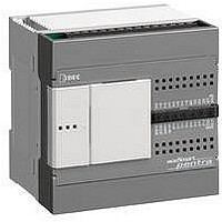
Programmable Logic Controller
Manufacturer
IDEC
Datasheet
1.FC5A-C16R2D.pdf
(2 pages)
Specifications of FC5A-C10R2D
No. Of Analog Outputs
4
Output Type
Relay
Supply Voltage Max
12VDC
No. Of Channels
10
Supply Voltage Min
10.2VDC
No. Of Analog Inputs
6
No. Of Digital Outputs
4
Lead Free Status / RoHS Status
Lead free / RoHS Compliant


Features
•
•
•
•
•
•
Specifications
General Specifications
Communication Port (RS232C, port1)
Notes:
1. Port 1 is modbus slave.
2. Port 2 is modbus master/slave.
3. 12V DC CPUs are not expandable.
MicroSmart Pentra 12V DC CPU Module
Part Number
Rated Power Voltage
Allowable Voltage
Range
Maximum
Power Consumption
Allowable Momentary
Power Interruption
Dielectric Strength
Insulation Resistance
Noise Resistance
Inrush Current
Power Supply Wire
Operating Temperature
Storage Temperature
Relative Humidity
Altitude
Pollution Degree
Corrosion Immunity
Grounding Wire
Vibration Resistance
Shock Resistance
Weight
Standards
Maximum Baud Rate
Maintenance Communication
User Communication
Data Link Communication
Cable
Isolation between Internal Circuit and
Communication Port
3 CPUs to choose from
-10 I/O, 16 I/O, 24 I/O
Fast processing spe
Built-in Modbus RTU, ASCII and TCP/IP
Support 32-bit and floating point math
Four built-in high speed inputs
-1pt: 50kHz single/dual phase
-3pts: 5kHz single phase
Field upgradeable firmware
FC5A-C10R2D
28W
240g
ed
5 to 9 Hz amplitude 3.5 mm, 9 to 150 Hz acceleration 9.8 m/s
(1G), 2 hours per axis on each of three mutually perpendicular
147 m/s
I/O terminals (coupling clamp): 1.5 kV, 50 ns to 1 µs
Operation: 0 to 2,000m, Transport: 0 to 3,000m
When mounted on a DIN rail or panel surface:
2
DC power terminals: 1.0 kV, 50 ns to 1 µs
mutually perpendicular axes (IEC61131-2)
(15G), 11 ms duration, 3 shocks per axis on three
EIA RS232C
57600 bps (maintenance communication)
Possible
Possible
Impossible
FC2A-KC4C, FC2A-KP1C, FC4A-KC2CA
Not isolated
10 MΩ minimum (500V DC megger)
10 MΩ minimum (500V DC megger)
Between power and
Between power and
UL1015 AWG22, UL1007 AWG18
Between I/O and
Between I/O and
10 ms (at rated power voltage)
10 to 95% (no condensation)
–25 to +70ºC (no freezing)
Free from corrosive gases
1,500V AC, 1 minute
1,500V AC, 1 minute
axes (IEC61131-2)
10.2 to 18.0V DC
FC5A-C16R2D
3.4W
UL1007 AWG16
260g
20A maximum
2 (IEC60664-1)
0 to +55ºC
12V DC
Applications
•
•
terminals:
terminals:
terminals:
terminals:
Solar industry
-solar traffic control & lighting
-remote solar pumping stations (oil & gas
industry)
-remote solar injection systems (oil & gas
industry)
-solar water pumping stations
-solar trackers
Vehicle/automotive
-handicap lifts, garbage trucks, bus/train
lighting & signage, cement truck mixers
FC5A-C24R2D
4.2W
310g
2
Function Specifications
*1. 1 step equals 6 bytes.
*2. Not including clock function processing time, data
Part Number
Control System
Instruction Words
Program Capacity
User Program Storage
Processing
Time
Max. I/O
Points
Internal Relay
Shift Register
Timer
Counter
Data Register
Self-diagnostic
Function
Input Filter
Catch Input/
Interrupt Input
Analog
Potentiometer
Port 1
Port 2 Communication
Adapter (option)
Clock Cartridge (option)
Memory Cartridge (option)
HMI Module (option)
link processing time, and interrupt processing time.
*3
Backup Data
Backup Duration
Battery
Charging Time
Battery Life
Replaceability
Maximum Counting
Frequency and High-
speed Counter Points
Counting Range
Operation Mode
Basic Instruction
END Processing
Input
Output
*4
Quantity
Data Range
*1
*2
FC5A-C10R2D
103 advanced
13.8 KB (2,300 steps)
6
4
RAM sum check, timer/counter preset value sum check, user program
Possible
Possible
Possible
Possible
Approx. 30 days (typical) at 25ºC after backup battery fully charged
syntax, WDT check, user program writing, power failure, watchdog
Keep data check, user program EPPROM sum check, user program
RS232C – maintenance communication, user communication,
Approx. 15 hours for charging from 0% to 90% of full charge
5 years in cycles of 9-hour charging and 15-hour discharging
Without filter, 3 to 15 ms (selectable in increments of 1 ms)
Internal relay, shift register, counter, data register
Minimum turn off pulse width: 150 µs maximum
Single/two-phase selectable: 50 kHz (1 point)
Minimum turn on pulse width: 40 µs maximum
Rotary encoder mode, adding counter mode
256 points (1-sec, 100-ms, 10-ms, 1-ms)
EEPROM (10,000 times rewritable)
Not possible to replace battery
1 point
256 points (adding, reversible)
Single-phase: 5 kHz (3 points)
Modbus slave communication
timer, data link connection
Lithium secondary battery
Four inputs (I2 through I5)
Stored program system
1.16 ms (1,000 steps)
FC5A-C16R2D
130 advanced
27 KB (4,500 steps)
9
7
Possible
Possible
Possible
Possible
0 to 65535 (16 bits)
*3. Not expandable with expansion I/O modules.
*4. Maintenance communication, user communication,
Total 4 points
2,048 points
2,000 points
modem communication, data link, Modbus master/
slave communication
128 points
42 basic
0.64 ms
0 to 255
12V DC
Model
FC5A-C24R2D
115 advanced
54 KB (9,000 steps)
14
10
2 points
Possible
Possible
Possible
Possible
New
Related parts for FC5A-C10R2D
Image
Part Number
Description
Manufacturer
Datasheet
Request
R

Part Number:
Description:
Accessory, RS232C Communications Module for MicroSmart Pentra
Manufacturer:
IDEC Corporation

Part Number:
Description:
INDICATOR INCANDESCENT LAMP, GREEN
Manufacturer:
IDEC
Datasheet:

Part Number:
Description:
LAMP, INDICATOR, INCAND, AMB
Manufacturer:
IDEC
Datasheet:
Part Number:
Description:
LAMP, INDICATOR, INCAND, GRN
Manufacturer:
IDEC
Datasheet:
Part Number:
Description:
LAMP, INDICATOR, INCAND, GRN
Manufacturer:
IDEC
Datasheet:
Part Number:
Description:
LAMP, INDICATOR, INCANDESCENT, RED
Manufacturer:
IDEC
Datasheet:
FC5A-C10R2D Summary of contents
Page 1
... Memory Cartridge (option) HMI Module (option) *1. 1 step equals 6 bytes. *2. Not including clock function processing time, data link processing time, and interrupt processing time. New 12V DC Model FC5A-C10R2D FC5A-C16R2D FC5A-C24R2D Stored program system 42 basic 103 advanced 130 advanced 115 advanced 13.8 KB (2,300 steps) ...
Page 2
... Specifications con’t Input Specifications Part Number FC5A-C10R2D FC5A-C16R2D FC5A-C24R2D Input Points 6 (6/1 common) 9 (9/1 common) Rated Input Voltage 12V DC sink/source input signal Input Voltage Range 10.2 to 18V DC I0 and I1 Rated Input Current I2 to I7, I10 to I15 and I1: 1.8 kΩ Input Impedance I2 to I7, I10 to I15: 2.0 kΩ ...