E5CN-Q2MT500 100/240AC Omron, E5CN-Q2MT500 100/240AC Datasheet - Page 16
E5CN-Q2MT500 100/240AC
Manufacturer Part Number
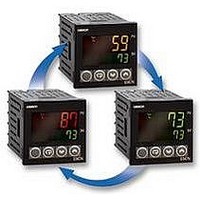
E5CN-Q2MT500 100/240AC
Description
TEMPERATURE CONTROL, DIGITAL
Manufacturer
Omron
Datasheet
1.E5CN-Q2MT500_100240AC.pdf
(26 pages)
Specifications of E5CN-Q2MT500 100/240AC
Svhc
No SVHC (15-Dec-2010)
Ip/nema Rating
IP66
No. Of Digits / Alpha
4
Power Consumption
7.5VA
Supply Voltage
24VAC
Digit Height
11mm
Display Technology
LCD
Meter Function
Temperature
Operating Temperature Range
-10°C To +55°C
Thermocouple Type
J, K, T, E, L, U, N, R, S, B, PT100
Operating Temperature Max
55°C
Operating Temperature Min
-10°C
Output Voltage Max
13.8V
Output Voltage Min
10.2V


■
Adjustment Level
C
C
C
C
C
C
C
l.adj
cmwt
lcr 1
lcr 2
s p-0
s p-1
s p-2
s p-3
ins h
ins l
a
ins
ct1
ct2
hb1
hb2
hs 1
hs 2
50.0
50.0
off
off
at
a
a
a
a
a
a
a
a
a
a
a
a
a
a
0.0
a
0.0
0.0
0.0
0.0
0.0
a
0.0
0.0
a
0.0
0
0
0
0
Displayed only once when
entering adjustment level.
Adjustment level
display
AT execute/cancel
Communications writing
Heater current value 1
monitor
Heater current value 2
monitor
Leakage current value
1 monitor
Leakage current value
2 monitor
Heater burnout 1
detection
Heater burnout 2
detection
SSR failure detection 1
SSR failure detection 2
SP 0
SP 1
SP 2
SP 3
Temperature input shift
Upper-limit
temperature input
Lower-limit
temperature input
SP used by multi-SP
2-point shift
1-point shift
Press the Level Key less than 1 s.
Press the Level Key less than 1 s.
Set either of these parameters.
C
C
C
C
C
C
c-s c
c-db
of-r
chys
s oak
wt-b
mV-s
mV-e
s pr t
ol-h
ol-l
hys
105.0
1.00
50.0
-5.0
233
off
off
a
a
8.0
0.0
1.0
a
1.0
a
a
0.0
0.0
a
a
a
a
40
a
a
a
a
a
a
p
i
d
1
Proportional band
Integral time
Derivative time
Cooling coefficient
Dead band
Manual reset value
Clear the offset during stabilization
of P or PD control.
Hysteresis (heating)
Hysteresis (cooling)
Soak time
Wait band
MV at stop
MV at PV error
SP ramp set value
MV upper limit
MV lower limit
Hysteresis settings
Heating/cooling
PID settings
Press the
Level
Key for at
least 3 s.
(Display
flashes
for at
least 1 s.)
Press the Level + Mode
Keys for at least 3 s.
Display flashes.
PV/MV
The time taken to move to the protect level can
be adjusted by changing the "Move to protect
level time" setting.
Starting in manual mode
C
Manual Control Level
pmoV
oapt
icpt
wtpt
pms k
pr lp
a
25
C
C
C
off
Protect Level
a
a
a
a
a
m-s p
s p-m
lcr 1
lcr 2
pr s t
s ktr
on
PID control only
0
0
1
0
a-m
ct1
ct2
r -s
r s et
25
25
a
r un
This protect level restricts movement
to the initial setting, communications
setting, and advanced function
setting levels.
a
a
a
a
a
Operation/adjustment
protection
Initial Setting/
Communications Protection
Setting change protection
Parameter mask enable
Displayed only when a
parameter mask is set.
Password to move to
protect level
Password setting
a
a
a
a
Move to protect level
Displayed only when a password
is set. Restricts moving to protect
level.
Restricts displaying and modifying
menus in operation, adjustment,
and manual control levels.
Protects changes to setups by
operating the front panel keys.
0.0
0.0
a
0.0
0.0
a
Power ON
0
0
0
0
Auto/manual switch
PID control only
Added when auto/manual
switching function is added.
Process value
Added when PV
display is added.
Process value/
set point
Multi-SP set
point setting
SP ramp monitor
Heater current value 1
monitor
Heater current value 2
monitor
Leakage current
value 1 monitor
Leakage current
value 2 monitor
Program start
Remaining soak
time monitor
Run/stop
Operation Level
Press the
Level Key
for at
least 1 s.
Press the Level + Mode
Keys for at least 1 s.
Starting in automatic
mode
Displayed only for models with communications.
Changes are effective after cycling power or after
a software reset.
C
C
C
C
C
C
C
C
C
al-1
al1h
al1l
al-2
al2h
al2l
al-3
al3h
al3l
ps el
u-no
s bit
pr ty
s dwt
c-o
bps
len
eVen
cwf
a
a
a
a
a
a
a
a
a
a
a
a
a
a
0.0
0.0
Communications
a
a
a
a
9.6
20
o
0
0
0
0
0
0
0
0
0
1
7
2
Setting Level
Alarm value 1
Upper-limit
alarm value 1
Lower-limit
alarm value 1
Alarm value 2
Upper-limit
alarm value 2
Lower-limit
alarm value 2
Alarm value 3
Upper-limit
alarm value 3
Lower-limit
alarm value 3
MV monitor (heating)
MV monitor (cooling)
Protocol setting
Switches between
CompoWay/F
(SYSWAY) and Modbus.
Communications
Unit No.
Baud rate
Data bits
Stop bits
Communications
parity
Send delay
Press the Level Key for at least 3 s.
(Display flashes for at least 1 s.)
Displays other than that for switching
between automatic and manual
CompoWay/F
(SYSWAY) only
Press the Level Key
less than 1 s.
Related parts for E5CN-Q2MT500 100/240AC
Image
Part Number
Description
Manufacturer
Datasheet
Request
R

Part Number:
Description:
Temperature Controller
Manufacturer:
Omron
Datasheet:

Part Number:
Description:
G6S-2GLow Signal Relay
Manufacturer:
Omron Corporation
Datasheet:
Part Number:
Description:
Compact, Low-cost, SSR Switching 5 to 20 A
Manufacturer:
Omron Corporation
Datasheet:
Part Number:
Description:
Manufacturer:
Omron Corporation
Datasheet:
Part Number:
Description:
Manufacturer:
Omron Corporation
Datasheet:
Part Number:
Description:
Manufacturer:
Omron Corporation
Datasheet:
Part Number:
Description:
Manufacturer:
Omron Corporation
Datasheet:
Part Number:
Description:
Manufacturer:
Omron Corporation
Datasheet:
Part Number:
Description:
Manufacturer:
Omron Corporation
Datasheet: