AZ8166 PANASONIC EW, AZ8166 Datasheet - Page 9
AZ8166
Manufacturer Part Number
AZ8166
Description
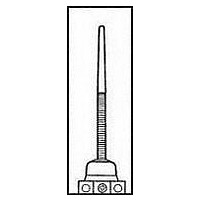
LIMIT SWITCH, FLEXIBLE ROD, SPDT
Manufacturer
PANASONIC EW
Datasheet
1.AZ8104.pdf
(24 pages)
Specifications of AZ8166
Actuator Style
Flexible Rod
Operating Force Max
0.88N
Contact Voltage Ac Max
250V
Contact Voltage Dc Max
125V
Contact Current Ac Max
5A
Contact Current Dc Max
400mA
Switch Terminals
Screw
Lead Free Status / RoHS Status
Lead free / RoHS Compliant


WIRING
1. Insulation distance greater than
Reinforced plastic with superior electrical
insulation characteristics is used in the
wiring and charging sections. Despite its
compactness, to maintain stable insula-
tion performance, the insulation distance
for each part is greater than 6.4 mm
without using an insulation sheet.
(Complies with UL, CSA, and VDE.)
2. Includes ground terminal
3. Loose stop terminals used.
Applicable wire
CAUTIONS
1. Over travel (O.T.)
1) When overtravel is too large, life is
shortened due to possible damage to the
mechanism. Please use in the following
appropriate range.
2. Ambient conditions
1) Because these switches are not of
immersion protected construction, their
use in water or oil should be avoided.
Also, locations where water or oil can
normally impinge upon the switch or
where there is an excessive accumula-
tion of dust should be avoided.
2) The use of these switches under the
following conditions should be avoided. If
the following conditions should become
necessary, we recommend consulting us
first.
• Use where there will be direct contact
with organic solvents, strong acids or
alkalis, or direct exposure to their vapors.
Spring ( 4 locations )
Vinyl cabtire cord (VCTF)
Vinyl cabtire cable (VCT)
600V vinyl insulation sealed cable
(VVF)
(AZ8111, 8112, 8122)
(AZ8104, 8107, 8108)
6.4 mm
(AZ8166, 8169)
Projection ( 8 locations )
Flexible Rod
Roller Arm
Groove ( 8 points )
Plunger
Types
Wire name
(unit: mm inch)
.787inch
15 to 20mm
.059 to .079inch
1.5 to 2.0mm
Overtravel
20 to 30°
Terminal
washer
(at the top)
Terminal
screw
.591 to
Wire-strand
2-wire
3-wire
4-wire
2-wire
2-wire
Grounding terminal
• Use where inflammable or corrosive
gases exist.
3) Use within an ambient temperature of
–20 to +60°C
do not allow it to freeze.)
4) In order to maintain the reliability at a
high level under practical conditions of
use, the actual operating conditions
should be checked for the benefit of the
quality of the product.
5) If OT is too big, the life of limit switch
will be shortened switching friction. Use it
with enough margin of OT. 70% of OT
standard value will be good for use.
6) Do not use the switch in a silicon
atmosphere. Case should be taken
where organic silicon rubber, adhesive,
sealing material, oil, grease or lead wire
generates silicon.
7) When wiring, do not connect the lead
wires directly to the terminals, but use
the crimp terminals and tighten them to a
torque of 0.39 to 0.59 N·m {4 to 6
kg·cm}.
8) Avoid use in excessively dusty envi-
ronments where actuator operation
would be hindered.
1.0 dia. to 1.2 dia.
0.75mm
2.0mm
0.75mm
Applicable wire
Conductor
0.75mm
1.6 dia.
2
2
2
·1.25mm
·1.25mm
–4 to
2
2
2
+140°F. (However,
Finished outside diameter
Round shape
6 dia. to 9 dia.
Flat shape Max. 9.4
Applicable fasten terminal
With insulated grip
Max. 14
Max. 10
Max. 6.4
.551
Max. 6.4
.394
.252
.252
3.0 to 3.7 dia.
.118 to .146
3.0 to 3.7 dia.
.118 to .146
Max. 14
Max. 10
Max. 6.4
Max. 6.4
.551
.394
Head block direction
change
(Roller arm, adjustable roller arm, adjustable rod types)
Actuator heads
may be moved
in 90° incre-
ments to any of
four directions,
by removing
one screw.
9) When used outdoors (in places where
there is exposure to direct sunlight or
rain such as in multistory car parks) or in
environments where ozone is generated,
the influence of these environments may
cause deterioration of the rubber materi-
al. Please consult us if you intend to use
a switch in environments such as these.
10) Do not store in places where organic
gas might be generated or in places of
high dust content or high humidity.
3. Installation
1) Tighten the three cover installation
screws equally. Tightening torque is 0.2
to 0.29 N·m (2 to 3 kg·cm).
2) Avoid having extra cord length pushed
into the cord vent. Any extra length when
wiring should be allowed to rest in its
natural position.
.252
.252
3.0 to 3.7 dia.
.118 to .146
3.0 to 3.7 dia.
.118 to .146
Max. 10
Max. 6.4
Max. 6.4
.394
.252
3.0 to 3.7 dia.
.118 to .146
.252
3.0 to 3.7 dia.
.118 to .146
VL (AZ8)
16
Fasten terminal
.630
N.C. use
Lock screw ( Black )
32
1.260
N.O. use
59
Related parts for AZ8166
Image
Part Number
Description
Manufacturer
Datasheet
Request
R

Part Number:
Description:
POWER RELAY, 24VDC, 30A, SPST-NO
Manufacturer:
PANASONIC EW
Datasheet:

Part Number:
Description:
POWER RELAY, SPDT, 12VDC, 10A, PC BOARD
Manufacturer:
PANASONIC EW

Part Number:
Description:
POWER RELAY, 24VDC, 5A, SPST-NO, PCB
Manufacturer:
PANASONIC EW
Datasheet:


Part Number:
Description:
SIGNAL RELAY, DPDT, 4.5VDC, 1A, SMD
Manufacturer:
PANASONIC EW
Datasheet:

Part Number:
Description:
SIGNAL RELAY, DPDT, 4.5VDC, 1A, THD
Manufacturer:
PANASONIC EW
Datasheet:

Part Number:
Description:
MINIATURE RELAY, DPDT, 24VDC, 2A, THD
Manufacturer:
PANASONIC EW


Part Number:
Description:
SIGNAL RELAY, DPDT, 5VDC, 2A, PC BOARD
Manufacturer:
PANASONIC EW
Datasheet:
Part Number:
Description:
SIGNAL RELAY, DPDT, 5VDC, 2A, SURFACE MOUNT
Manufacturer:
PANASONIC EW
Datasheet:
Part Number:
Description:
SIGNAL RELAY, DPDT, 5VDC, 2A, PC BOARD
Manufacturer:
PANASONIC EW
Datasheet:


Part Number:
Description:
PHOTOMOS RELAY, 60VDC, 400mA
Manufacturer:
PANASONIC EW
Datasheet:

Part Number:
Description:
PHOTOMOS RELAY, 400V, 150mA
Manufacturer:
PANASONIC EW
Datasheet: