F3SN-A0207P14 Omron, F3SN-A0207P14 Datasheet - Page 32
F3SN-A0207P14
Manufacturer Part Number
F3SN-A0207P14
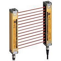
Description
Safety Light Curtain
Manufacturer
Omron
Series
F3SN-Ar
Datasheet
1.F3SN-A0207P14.pdf
(40 pages)
Specifications of F3SN-A0207P14
Beam Spacing
9mm
Control Output Type
PNP
No. Of Beams
23
Protection Height
207mm
Sensing Range Max
7m
Supply Voltage Max
24VDC
Peak Reflow Compatible (260 C)
No
Light Curtain Type
Safety
Lead Free Status / RoHS Status
Contains lead / RoHS non-compliant


Do not use the product in atmospheres or environments that exceed
product ratings.
Installation
How to Prevent Mutual Interference
Series connection (Up to 3 sets, 240 beams, sensor
models ending in -01, -03, -04, and -05 are required for
series connection)
Two or more pairs of the F3SN-A can be connected in series. When
connected in series, the F3SN-A sensors generate beams in a
time-sharing manner. Thus, they prevent mutual interference and
ensure safety.
When not connected
Refer to “Precautions for All Safety Sensors” for information on
preventing mutual interference of Safety Light Curtains that are not
connected in series.
Cable for
connection
F39-JCR2B or
F39-JCR5B or
F39-JC3B
Receiver 2
Emitter 1
Emitter 2
Emitter 1
Do not connect the emitter and
receiver in series, or a lockout
condition will result.
Precautions for Correct Use
Incorrect
Correct
http://www.ia.omron.com/
Receiver 1
Receiver 2
Receiver 1
Emitter 2
Emitter 1
Emitter 2
Do not combine an emitter with a
receiver of a different pair.
This will cause a lockout condition
and detection of objects will be
disabled.
Emitter
Incorrect
Receiver 2
Receiver 1
Receiver
Installation
How to attach Mounting Bracket (F39-L19/L20)
F39-L19
Brackets and screws included in one set
• Mounting bracket (1) .....1
• Mounting bracket (2) .....1
• M5 × 12 screw ..............1
Emitter/
receiver-mounted
face
F39-L19
F39-L20
To fully utilize the performance of
sensors, locate the F39-L19/L20
mounting brackets in the number
satisfying the dimensions “A” and
“B” in the sensor longitudinal
direction.
Note: When installing sensors at
Mounting bracket
M5 × 12
screw
For the F39-L19
Spacing “A”: 670 mm max.
For the F39-L20
Spacing “B”: 400 mm max.
(c)Copyright OMRON Corporation 2007 All Rights Reserved.
locations susceptible to
vibration and shock, increase
the number of mounting
brackets.
Mounting bracket (2)
M5 × 12 screw
M4 × 8 screw
F3SN-A/F3SN-B/F3SH-A
Screw × length (mm) Tightening torque
Mounting
bracket (1)
Emitter/
receiver-mounted
face
Toothed washer
(2 pcs.)
F39-L20
M4 × 8 screw
Brackets and screws included in one set
• Mounting bracket (1) .....1
• Mounting bracket (2) .....1
• M5 × 12 screw ..............1
• Mounting bracket (3) .....1
• M4 × 8 screw ................1
• Toothed washer ............2
[Brackets (1) and (2), M5 × 12 screw]
A/2
A/2
A
A
2.0 N·m
1.2 N·m
F39-L19
Mounting
bracket (3)
B/2
B/2
B
B
32
Related parts for F3SN-A0207P14
Image
Part Number
Description
Manufacturer
Datasheet
Request
R

Part Number:
Description:
Safety Light Curtain
Manufacturer:
Omron
Datasheet:

Part Number:
Description:
Safety Light Curtains 21-125 BEAM 387mm HT NO CONN 14mm DET DIA
Manufacturer:
Omron
Part Number:
Description:
Safety Light Curtains 21-125 BEAM 477mm HT NO CONN 14mm DET DIA
Manufacturer:
Omron
Part Number:
Description:
Safety Light Curtains 21-125 BEAM 675mm HT NO CONN 14mm DET DIA
Manufacturer:
Omron
Part Number:
Description:
Safety Light Curtains 13-120 BEAM 862mm HT NO CONN 25mm DET DIA
Manufacturer:
Omron
Part Number:
Description:
Safety Light Curtains 13-120 BM 1222mm HT NO CONN 25mm DET DIA
Manufacturer:
Omron
Part Number:
Description:
Safety Light Curtains 13-120 BM 1402mm HT NO CONN 25mm DET DIA
Manufacturer:
Omron
Part Number:
Description:
Safety Light Curtains 13-120 BM 1387mm HT NO CONN 25mm DET DIA
Manufacturer:
Omron
Part Number:
Description:
Safety Light Curtains 13-120 BM 1762mm HT NO CONN 25mm DET DIA
Manufacturer:
Omron
Part Number:
Description:
Safety Light Curtains 13-120 BEAM 802mm HT NO CONN 25mm DET DIA
Manufacturer:
Omron

Part Number:
Description:
G6S-2GLow Signal Relay
Manufacturer:
Omron Corporation
Datasheet:
Part Number:
Description:
Compact, Low-cost, SSR Switching 5 to 20 A
Manufacturer:
Omron Corporation
Datasheet:
Part Number:
Description:
Manufacturer:
Omron Corporation
Datasheet: