D4NL-1AFA-B Omron, D4NL-1AFA-B Datasheet - Page 15
D4NL-1AFA-B
Manufacturer Part Number
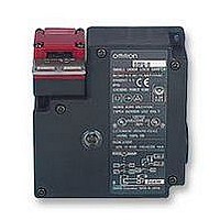
D4NL-1AFA-B
Description
SAFETY SWITCH
Manufacturer
Omron
Specifications of D4NL-1AFA-B
Contact Voltage Ac Max
240V
Contact Voltage Dc Max
24V
Contact Current Ac Max
10A
Contact Current Dc Max
200mA
Switch Terminals
Screw
Svhc
No SVHC (15-Dec-2010)
Approval Bodies
EN60747-5-1, IEC 947-5-1, EN1088,
Contact Configuration
SPST-NC / SPST-NO
Lead Free Status / Rohs Status
Lead free / RoHS Compliant


AA-72
Guard Lock Safety-door Switch
When the door is closed (with the Operation Key inserted), it may be
pulled beyond the set zone because of, for example, the door’s
weight, or the door cushion rubber. Also, if a load is applied to the
Operation Key, the door may fail to unlock properly. Use hooks to
ensure that the door stays within the set zone.
J.S.T. Mfg Co.
When connecting to the terminals via insulating tube and M3.5
crimp terminals, cross the crimp terminals as shown above so that
they do not rise up onto the case or the cover. Applicable lead wire
size: AWG20 to AWG18 (0.5 to 0.75mm
When connecting lead wires directly to terminals, perform wiring
securely so that there are no loose wire strands.
Do not push crimp terminals into gaps in the case interior. Doing so
may cause damage or deformation of the case.
Use lead wires of an appropriate length. Not doing so may cause
the cover to rise.
Use crimp terminals not more than 0.5 mm in thickness. Otherwise,
they will interfere with other components inside the case. The crimp
terminals shown below are not more than 0.5 mm thick.
Switch the release key to the UNLOCK position.
Remove the four screws of the head to enable changing the
mounting direction of the head. The head can be mounted in four
directions.
Ensure that no foreign material enters the interior of the Switch.
Also, insert the head until the insertion line engraved on the head
is hidden by the reference line on the Switch, as shown in the
following diagram.
Return the release key to the LOCK position.
OMRON SCIENTIFIC TECHNOLOGIES, INC.
USA
Set zone
(0.5 to 3 mm)
Tel. 1/888/510-4357
FV0.5-3.7
D dia.
Canada
D4NL
Operation key
2
).
Tel. 1/866/986-6766
dz dia.
AWG20 (0.5 mm
2
)
For the Latest Information
On the Internet: www.sti.com or www.omron.ca
Use a connector with a screw section not exceeding 11 mm, other-
wise the screws will protrude into the case interior. The connectors
given in the following table have connectors with screw sections not
exceeding 11 mm.
Use the following connectors to ensure conformance to IP67.
Use LAPP connectors together with Seal Packing (JPK-16, GP-13.5,
or GPM20), and tighten with the applicable torque. Seal Packing is
sold separately.
G
Pg13.5
M20
Connect a recommended connector to the opening of the conduit
and tighten the connector to the proper torque. The case may be
damaged if an excessive tightening torque is applied.
To ensure IP67 degree of protection, wrap sealing tape around the
conduit end of the connector.
Be sure that the outer diameter of the cable connected to the con-
nector is correct.
Attach and tighten a conduit cap to the unused conduit opening
when wiring. The conduit cap is provided with the Switch.
Do not touch the solenoid. The temperature of the solenoid
increases when current is passed.
1
/
2
LAPP
OHM
ELECTRIC CO.
LAPP
LAPP
ST-PF1/2
5380-1002
OA-W1609
OA-W1611
S-13.5
5301-5030
ST-M20
5311-1020
1.5
6.0 to 12.0 mm
7.0 to 9.0 mm
9.0 to 11.0 mm
5.0 to 12.0 mm
7.0 to 13.0 mm
Related parts for D4NL-1AFA-B
Image
Part Number
Description
Manufacturer
Datasheet
Request
R

Part Number:
Description:
Safety Limit Switch
Manufacturer:
Omron
Datasheet:
Part Number:
Description:
Door Switch, 1NC/1NO Slo
Manufacturer:
Omron
Datasheet:
Part Number:
Description:
Limit Switch
Manufacturer:
Omron
Datasheet:
Part Number:
Description:
G1/2,1NC/1NO,1NC,1NO,Plst,lck
Manufacturer:
Omron
Datasheet:
Part Number:
Description:
Interlock Switch
Manufacturer:
Omron
Datasheet:
Part Number:
Description:
Limit Switch
Manufacturer:
Omron
Datasheet:
Part Number:
Description:
Locking Interlock Switch
Manufacturer:
Omron
Datasheet:
Part Number:
Description:
Interlock Door Switch
Manufacturer:
Omron
Datasheet:
Part Number:
Description:
Safety Door Switch
Manufacturer:
Omron
Datasheet:
Part Number:
Description:
Safety Door Switch
Manufacturer:
Omron
Datasheet:
Part Number:
Description:
Basic / Snap Action / Limit Switches 2NC+2NC SOL lock
Manufacturer:
Omron
Datasheet:
Part Number:
Description:
Basic / Snap Action / Limit Switches 3NC+1NC/1NO Metal head SOL.RLS
Manufacturer:
Omron
Datasheet:
Part Number:
Description:
SAFETY SWITCH
Manufacturer:
Omron
Datasheet:
Part Number:
Description:
SAFETY INTERLOCK SWITCH
Manufacturer:
Omron
Datasheet: