HS1B-02R IDEC, HS1B-02R Datasheet - Page 3
HS1B-02R
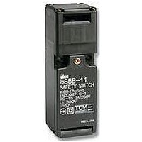
Manufacturer Part Number
HS1B-02R
Description
SWITCH, SAFETY INTERLOCK, 2NC, 10A
Manufacturer
IDEC
Datasheet
1.HS1B-02R.pdf
(8 pages)
Specifications of HS1B-02R
Contact Configuration
DPST-NC
Contact Voltage Ac Max
125V
Contact Voltage Dc Max
250V
Contact Current Ac Max
10A
Contact Current Dc Max
8A
Switch Terminals
Screw
Circuitry
DPST-NC
Lead Free Status / RoHS Status
Lead free / RoHS Compliant


Door Interlock Switches
HS1B
Door/
Switch
Status
Door
HS1B-11
(1NO-1NC)
Circuit
Diagram
Main
Circuit
Aux.
Circuit
HS1B-02
(2NC)
Circuit
Diagram
Main
Circuit
Aux.
Circuit
Application Examples and Circuit Diagrams
1. Main Circuit: used to enable the machine to start only when the main circuit is closed.
2. Terminals + and - are used for the LED indicator, and are isolated from door status.
Auxiliary Circuit: used to indicate whether the main circuit or door is open or closed.
Wire the terminals only when needed.
USA: 800-262-IDEC
•
•
Door Closed
Machine ready to operate
3-4: Closed
3-4: Closed
1-2: Closed
1-2: Open
Status 1
-
-
+
+
1
2
3
4
1
2
3
4
Canada: 888-317-IDEC
•
•
Door opened
Machine cannot be started
1-2: Closed
3-4: Open
3-4: Open
1-2: Open
Status 2
-
-
+
+
1
2
3
4
1
2
3
4
HS1B Series
363
Related parts for HS1B-02R
Image
Part Number
Description
Manufacturer
Datasheet
Request
R

Part Number:
Description:
HS1B-114R-G Sfty Swtch 1NO-1NC W/indicator G1/2
Manufacturer:
IDEC
Datasheet:
Part Number:
Description:
Hs1b Series Full Size Interlock Switch
Manufacturer:
IDEC Corporation
Datasheet:
Part Number:
Description:
Cable; Between IDEC MicroSmart (port 1 or 2) and HG2F/3F/4F; 5 ft.
Manufacturer:
IDEC Corporation
Datasheet:
Part Number:
Description:
Cable; Between IDEC Micro^3C/ONC/MicroSmart (port 2) PLCs and HG2F/3F/4F; 5 ft.
Manufacturer:
IDEC Corporation
Datasheet:
Part Number:
Description:
Angled Key for Idec HS6B Safety Switch
Manufacturer:
IDEC Corporation
Datasheet:
Part Number:
Description:
Accessory, L-Shaped Key for Idec HS5B and HS5E Safety Switch
Manufacturer:
IDEC Corporation
Datasheet:
Part Number:
Description:
Accessory, Straight Key for Idec HS5B and HS5E Safety Switch
Manufacturer:
IDEC Corporation
Datasheet:
Part Number:
Description:
Straight Key for Idec HS6B Safety Switch
Manufacturer:
IDEC Corporation
Datasheet:
Part Number:
Description:
LIGHT TOWER 3 TIER RED/AMBER/GREEN 24VAC/DC WALL MOUNT
Manufacturer:
IDEC Corporation
Datasheet:
Part Number:
Description:
Flat Lens, 24V AC/DC, 1m Cable Length, Alternate: Red Green Color, IP67
Manufacturer:
IDEC Corporation
Datasheet:

Part Number:
Description:
IC LN-DRVR ARINC 429 16-SBDIP
Manufacturer:
Intersil
Datasheet:
Part Number:
Description:
IC,LINE TRANSCEIVER,CMOS,1 DRIVER,2 RCVR,DIP,40PIN,CERAMIC
Manufacturer:
Intersil
Datasheet:
Part Number:
Description:
Manufacturer:
Intersil
Datasheet:
Part Number:
Description:
Manufacturer:
Intersil
Datasheet:

Part Number:
Description:
ARINC 429 Bus Interface Line Driver Circuit
Manufacturer:
Intersil Corporation