HS5B-11B IDEC, HS5B-11B Datasheet - Page 3
HS5B-11B
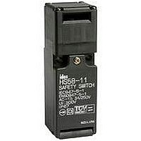
Manufacturer Part Number
HS5B-11B
Description
SWITCH, SAFETY INTERLOCK, 1NO/1NC, 10A
Manufacturer
IDEC
Datasheet
1.HS5B-02B.pdf
(9 pages)
Specifications of HS5B-11B
Contact Configuration
SPST-NO / SPST-NC
Contact Voltage Ac Max
250V
Contact Voltage Dc Max
250V
Contact Current Ac Max
10A
Contact Current Dc Max
8A
Switch Terminals
Screw
Lead Free Status / RoHS Status
Lead free / RoHS Compliant


B1
HS5B Series
HS5B - using the straight key (HS9Z-A51)
B1-10
HS5B-11B (1NO-1NC)
Door/
Switch
Status
Door
Circuit
Diagram
Main
Circuit
Aux.
Circuit
1. Main Circuit: used to enable the machine to start only
2. Auxiliary Circuit: used to indicate whether the
when the main circuit is closed.
machine circuit or door is open or closed.
• Door Closed
• Machine ready to operate
3-4: Closed
1-2: Open
RP: Actuator Mounting
Status 1
Reference Position
Actuator Stop
Actuator
www.idec.com
6.2
26.4
1
2
3
4
5.2
42.2
• Door opened
• Machine cannot be started
3-4: Open
1-2: Closed
36.2
Application Examples and Circuit Diagrams
Status 2
91
1
2
3
4
Conduit Port
Dimensions
USA: (800) 262-IDEC or (408) 747-0550, Canada: (888) 317-IDEC
4-M4 Screws
HS5B-02B (2NC)
Door/
Switch
Status
Door
Circuit
Diagram
Main
Circuit
Aux.
Circuit
36
5.2
20 to 22
Mounting Hole Layout
Safety Products
• Door Closed
• Machine ready to operate
3-4: Closed
1-2: Closed
26.4
Actuator Stop
6.2
Actuator
Status 1
1
2
3
4
6 1.0
36.2
• Door opened
• Machine cannot be started
3-4: Open
1-2: Open
91
Status 2
Conduit Port
All dimensions in mm.
1
2
3
4
Related parts for HS5B-11B
Image
Part Number
Description
Manufacturer
Datasheet
Request
R

Part Number:
Description:
INTERLOCK SWITCH 1NO/1NC G1/2
Manufacturer:
IDEC Corporation
Datasheet:
Part Number:
Description:
Switch, Safety, Interlocking, HS5B Series, 2NC, G1/2 Conduit Port
Manufacturer:
IDEC Corporation
Datasheet:
Part Number:
Description:
Safety Swtich 2NC Metal Head
Manufacturer:
IDEC
Datasheet:
Part Number:
Description:
Cable; Between IDEC MicroSmart (port 1 or 2) and HG2F/3F/4F; 5 ft.
Manufacturer:
IDEC Corporation
Datasheet:
Part Number:
Description:
Cable; Between IDEC Micro^3C/ONC/MicroSmart (port 2) PLCs and HG2F/3F/4F; 5 ft.
Manufacturer:
IDEC Corporation
Datasheet:
Part Number:
Description:
Angled Key for Idec HS6B Safety Switch
Manufacturer:
IDEC Corporation
Datasheet:
Part Number:
Description:
Accessory, L-Shaped Key for Idec HS5B and HS5E Safety Switch
Manufacturer:
IDEC Corporation
Datasheet:
Part Number:
Description:
Accessory, Straight Key for Idec HS5B and HS5E Safety Switch
Manufacturer:
IDEC Corporation
Datasheet:
Part Number:
Description:
Straight Key for Idec HS6B Safety Switch
Manufacturer:
IDEC Corporation
Datasheet:
Part Number:
Description:
LIGHT TOWER 3 TIER RED/AMBER/GREEN 24VAC/DC WALL MOUNT
Manufacturer:
IDEC Corporation
Datasheet:
Part Number:
Description:
INDICATOR INCANDESCENT LAMP, GREEN
Manufacturer:
IDEC
Datasheet:

Part Number:
Description:
LAMP, INDICATOR, INCAND, AMB
Manufacturer:
IDEC
Datasheet:
Part Number:
Description:
LAMP, INDICATOR, INCAND, GRN
Manufacturer:
IDEC
Datasheet:
Part Number:
Description:
LAMP, INDICATOR, INCAND, GRN
Manufacturer:
IDEC
Datasheet:
Part Number:
Description:
LAMP, INDICATOR, INCANDESCENT, RED
Manufacturer:
IDEC
Datasheet: