SI-HG63FQDL BANNER ENGINEERING, SI-HG63FQDL Datasheet - Page 4
SI-HG63FQDL
Manufacturer Part Number
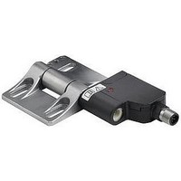
SI-HG63FQDL
Description
SWITCH, SAFETY INTERLOCK, 3NC/3NO, 3A
Manufacturer
BANNER ENGINEERING
Datasheet
1.SI-HG63A.pdf
(8 pages)
Specifications of SI-HG63FQDL
Contact Voltage Ac Max
230V
Contact Voltage Dc Max
24V
Contact Current Ac Max
3A
Contact Current Dc Max
1A
Switch Terminals
Quick Connect


Fine-Adjusting the Switch Point Setting
The adjustment screw can be used to adjust the setting by ±1.5°. This can be useful to
compensate for deviations during installation or later (a misplaced stop or machine vibration,
for example). To make the adjustment, insert the supplied screwdriver into the slot of the
arrow (Figure 2c) and turn clockwise to increase or counterclockwise to decrease the setting.
For most applications, adjust the angle to its functional minimum position.
Relocating the Switch Point Setting or Repositioning the Hinge
The switch point setting can be changed at a later date (for example, to mount in a
new location). Changing the setting requires replacement of the red plastic washer (see
Accessories for a kit that includes a replacement washer).
The hinge must be removed from the switch component in order to remove the earlier switch
point setting. The hinge may then be reinstalled on the same side of the switch as before, or
it may be installed to the opposite side. (Thus a left-hand hinge may be converted to a right-
hand hinge, and vice versa.)
To perform either task:
1. Remove the screws fastening the hinge to the switch using the supplied tool. (Figure 3a.)
2. Insert a flat-blade screwdriver between the hinge housing and the plastic plug, to gently
3. Remove the hinge portion from the switch. Lift the red plastic washer from the switch.
4. Align the switch cylinder arrow with mark “A” on the switch housing. (An SW8-size hex
5. Gently press and turn the switch element into the enclosure, until the switch cylinder arrow
6. Press the switch element into the enclosure again, until it reaches the internal stop. Install
7. If changing the hinge position on the switch (changing from a left hinge to a right, for
8. Fix the new switch point setting as required.
Hinge Switches –
Retain the screws for later reuse.
pry the plastic plugs out. Retain the plastic plugs for later reuse. (Figure 3b.)
Discard the plastic washer; it cannot be reused. (Figures 3c and 3d.)
wrench is recommended, for easy rotation.) (Figure 3e.)
aligns with mark “B” on the switch housing. (Figure 3f.)
a new red plastic washer (from the accessories bag included with the switch) onto the
switch cylinder. (Figure 3g.)
example), remove the rectangular plug from the switch housing and attach the hinge to
that side. Install the hinge onto the switch and rotate 30° to seat. Fasten the switch to the
hinge using the supplied tool and the screws removed in step 1. (Figure 3h.) (Countersunk
screw max. torque: 2 Nm.)
P/N 129465
SI-HG63 Series
Banner Engineering Corp. • Minneapolis, MN U.S.A.
www.bannerengineering.com • Tel: 763.544.3164
Figure . Setting the switch point
b. Tighten screw with supplied bit
c. When the red color ring in the gap goes
a. Move door or hatch to closed position
(max. torque Nm).
from red to green, fixation has been
done correctly.
and secure.
Switch Point
Adjustment
Related parts for SI-HG63FQDL
Image
Part Number
Description
Manufacturer
Datasheet
Request
R

Part Number:
Description:
SI-HG63-W-10 ACCESSORY CODING RING-10 PACK
Manufacturer:
BANNER ENGINEERING
Part Number:
Description:
Replacement Accessory Kit
Manufacturer:
BANNER ENGINEERING
Datasheet:

Part Number:
Description:
PCB FUSE CARRIER AUTO TYPE 15A
Manufacturer:
Phoenix Contact
Datasheet:
Part Number:
Description:
PCB FUSE CARRIER AUTO TYPE 30A
Manufacturer:
Phoenix Contact
Datasheet:

Part Number:
Description:
Photoelectric Sensor
Manufacturer:
BANNER ENGINEERING
Datasheet:

Part Number:
Description:
Photoelectric Sensor
Manufacturer:
BANNER ENGINEERING
Datasheet:
Part Number:
Description:
LEDIR70XD4-XM-81039 MAX INTENS STROBE ONLY NO BANNER MARKS
Manufacturer:
BANNER ENGINEERING
Part Number:
Description:
M18SP6DL-72225 LABELED MOELLER NO BANNER MARKINGS BULK PACK
Manufacturer:
BANNER ENGINEERING
Part Number:
Description:
Photoelectric Sensor
Manufacturer:
BANNER ENGINEERING
Datasheet:

Part Number:
Description:
Programmable Indicator Light
Manufacturer:
BANNER ENGINEERING
Datasheet:
Part Number:
Description:
INDICATOR LED PANEL 50MM GRN/RED/YEL 30V
Manufacturer:
BANNER ENGINEERING
Datasheet:
Part Number:
Description:
Programmable Indicator Light
Manufacturer:
BANNER ENGINEERING
Datasheet: