SI-QS90ME BANNER ENGINEERING, SI-QS90ME Datasheet - Page 4
SI-QS90ME
Manufacturer Part Number
SI-QS90ME
Description
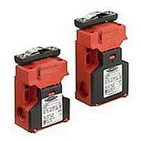
SWITCH, SAFETY INTERLOCK, 2NC, 10A
Manufacturer
BANNER ENGINEERING
Datasheet
1.SI-QS90ME.pdf
(12 pages)
Specifications of SI-QS90ME
Contact Configuration
DPST-NC
Contact Voltage Ac Max
230V
Contact Voltage Dc Max
24V
Contact Current Ac Max
10A
Contact Current Dc Max
6A
Switch Terminals
Screw
Contact Current Max
10A
Circuitry
DPST-NC


Machine Safety Switches –
IMPORTANT: A safety switch must be installed in a manner which discourages
tampering or defeat. Mount switches to prevent bypassing of the switching
function at the terminal chamber. A switch and its actuator must never be used as
a mechanical stop. Overtravel may cause damage to switch.
1. Temporarily mount the switch body in place, with its actuator inserted, using the
NOTE: The slotted holes in the switch body must ONLY be used for alignment
2. Slide the switch body on its temporary fasteners to locate and mark the actuator
All mounting hardware is supplied by the user. The fasteners must be of sufficient
strength to guard against incidental breakage. Use of permanent fasteners or locking
hardware is recommended to prevent loosening or displacement of the actuator and
switch body.
NOTE: The non-adjustable in-line actuator includes floating sleeves in the mounting
3. Engage the actuator into the switch body. Align them so that the actuator is fully
4
slotted 5 mm holes. See Figure 2.
mounting position. Remove the actuator from the switch body and mount it using
tamper-resistant 5 mm (#10) hardware (e.g., Torx-head screws, rivets, etc.).
engaged. Fasten the switch body in place using two tamper-resistant 5 mm (#10)
screws through the two round holes. Check switch engagement for misalignment and
binding.
P/N 49370 rev. E
holes to allow some forgiveness for switch-to-actuator alignment. Take care to not
over-tighten the actuator fasteners so as to allow this movement. This actuator
also includes a snap-on cap to cover the fasteners (see Figure 2).
during installation. The round 5 mm holes (only) must be used for
permanent mounting to prevent loosening or displacement of the actuator
and the switch body. Only M5 (#10) screws (user supplied), should be used.
Mechanical Installation
SI-QS75 and SI-QS90 Series Flat Pack Style
Banner Engineering Corp. • Minneapolis, MN U.S.A.
www.bannerengineering.com • Tel: 763.544.3164
Figure . Mounting holes installation
hazard point through an opened guard
(or any opening) before hazardous
machine motion has completely stopped.
Please reference OSHA CFR 1910.217
and ANSI B11 standards (see page 2) for
information on determining safety distances
and safe opening sizes for your guarding
devices.
Snap-On Cap
M5 (#10) Clearance
WARNING . . .
It must not be possible for
personnel to reach any
Use for
permanent mounting
Use ONLY for
alignment
during installation
Related parts for SI-QS90ME
Image
Part Number
Description
Manufacturer
Datasheet
Request
R

Part Number:
Description:
SI-QS-SSA-4 STANDARD ACTUATOR
Manufacturer:
BANNER ENGINEERING

Part Number:
Description:
Photoelectric Sensor
Manufacturer:
BANNER ENGINEERING
Datasheet:

Part Number:
Description:
Programmable Indicator Light
Manufacturer:
BANNER ENGINEERING
Datasheet:
Part Number:
Description:
INDICATOR LED PANEL 50MM GRN/RED/YEL 30V
Manufacturer:
BANNER ENGINEERING
Datasheet:
Part Number:
Description:
Programmable Indicator Light
Manufacturer:
BANNER ENGINEERING
Datasheet: