SI-QS75MFC BANNER ENGINEERING, SI-QS75MFC Datasheet - Page 3
SI-QS75MFC
Manufacturer Part Number
SI-QS75MFC
Description
SWITCH, SAFETY INTERLOCK, 1NO, 10A
Manufacturer
BANNER ENGINEERING
Type
Interlockr
Specifications of SI-QS75MFC
Contact Configuration
SPST-NC
Contact Voltage Ac Max
230V
Contact Voltage Dc Max
24V
Contact Current Ac Max
10A
Contact Current Dc Max
6A
Switch Terminals
Screw
Circuitry
SPST-NC
Actuator Type
Flexible
Contact Form
1 NO
Current, Rating
10/6 AAC/ADC
Function
Safety
Ip Rating
IP65
Number Of Poles
1
Number Of Positions
1
Standards
UL Listed, CSA Certified, CE Marked
Temperature Rating
-30 to +80 °C
Termination
Screw
Voltage, Rating
230/24 VAC/VDC
Lead Free Status / Rohs Status
RoHS Exempt Product


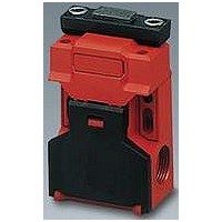
Figure 1. Rotating the actuator head and accessing the wiring chamber
NOTE:
††
SI-QS90MF
SI-QS90MFF
(Direct replacement for models
SI-QS90MRHF and SI-QS90MRVF)
SI-QS90MFHF
(High Force)
SI-QS75MC
SI-QS75MFC
(Direct replacement for models
SI-QS75MRHC and SI-QS75MRVC)
SI-QS75MCHF
(High Force)
†
High Force: 50 N (11.25 lbf) holding force integrated into switch. Use SI-QS-SSA In-Line
Actuator only; also see accessory SI-QS-100 on page 9.
A kit contains an interlock and actuator. Individual interlock bodies or actuators are for
replacement purposes only. See Warning on page 10.
Banner Engineering Corp. • Minneapolis, MN U.S.A.
where the normally closed safety contact is fully open.
www.bannerengineering.com • Tel: 763.544.3164
††
††
This symbol is used in the switching diagrams to identify the point in actuator travel
Model
Kit
Machine Safety Switches –
†
SI-QS-SSA-4
SI-QS-SSA-4
SI-QS-SSU
SI-QS-SSA
SI-QS-SSU
SI-QS-SSA
Actuator
Stamped
Die-Cast
Stamped
Die-Cast
Flexible
Flexible
Type
In-Line
In-Line
In-Line
In-Line
†
SI-QS75CHF
Interlock
SI-QS90F
SI-QS90F
SI-QS75C
Body
Models, continued
†
Overview
(Actuator Engaged)
Configuration
15
25
33
SI-QS75 and SI-QS90 Series Flat Pack Style
Two N.C. and One N.O. Contact
11
Contact
One N.O. Contact
16
26
34
12
(Actuator Removed)
Configuration
15
25
33
Easy Access
The wiring chamber is accessed via a
hinged door. Simply insert a flat-blade
screwdriver, as shown, and pry gently
down to open.
Rotating Actuator Head
The actuator head may be rotated 180° to
create four possible actuator engagement
locations. To rotate the head, first open
the wiring chamber door, as shown, left.
Then, using a small flat-blade screwdriver,
dislodge the two locking tabs located on
the backside of the switch. Lift the head
straight off of the switch body. Rotate the
head, as shown, and reinstall it on the
switch body.
11
Contacts:
Contact
16
26
34
12
Open
Disengaged
Engaged
Disengaged
Engaged
Closed
Switching
Diagrams
P/N 49370 rev. E
Transition
0 (0)
6.2 (0.24)
7.2 (0.28)
21.5 (0.85)
mm (in)
0 (0)
3.0 (0.12)
3.5 (0.14)
5.0 (0.20)
21.5 (0.85)
mm (in)
Related parts for SI-QS75MFC
Image
Part Number
Description
Manufacturer
Datasheet
Request
R

Part Number:
Description:
Photoelectric Sensor
Manufacturer:
BANNER ENGINEERING
Datasheet:

Part Number:
Description:
Photoelectric Sensor
Manufacturer:
BANNER ENGINEERING
Datasheet:

Part Number:
Description:
LEDIR70XD4-XM-81039 MAX INTENS STROBE ONLY NO BANNER MARKS
Manufacturer:
BANNER ENGINEERING
Part Number:
Description:
M18SP6DL-72225 LABELED MOELLER NO BANNER MARKINGS BULK PACK
Manufacturer:
BANNER ENGINEERING
Part Number:
Description:
M18SP6DLQ-72226 LABLED MOELLER NO BANNER MARKINGS BULK PACK
Manufacturer:
BANNER ENGINEERING
Part Number:
Description:
M18SP6L-72223 LABELED MOELLER NO BANNER MARKINGS BULK PACK
Manufacturer:
BANNER ENGINEERING
Part Number:
Description:
M18SP6LQ-72224 LABELED MOELLER NO BANNER MARKINGS BULK PACK
Manufacturer:
BANNER ENGINEERING
Part Number:
Description:
P4D1-77908 P4 DRIVER GENERIC NO BANNER MARKINGS RESALE TO CUSTOMER
Manufacturer:
BANNER ENGINEERING
Part Number:
Description:
Photoelectric Sensor
Manufacturer:
BANNER ENGINEERING
Datasheet:

Part Number:
Description:
Programmable Indicator Light
Manufacturer:
BANNER ENGINEERING
Datasheet:
Part Number:
Description:
INDICATOR LED PANEL 50MM GRN/RED/YEL 30V
Manufacturer:
BANNER ENGINEERING
Datasheet:
Part Number:
Description:
Programmable Indicator Light
Manufacturer:
BANNER ENGINEERING
Datasheet: