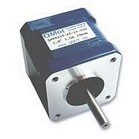
QSH4218-35-10-027 TRINAMIC, QSH4218-35-10-027 Datasheet - Page 9

QSH4218-35-10-027
Manufacturer Part Number
QSH4218-35-10-027
Description
STEPPER MOTOR, 1.8DEG, 1A, 0.27NM
Manufacturer
TRINAMIC
Datasheet
1.QSH4218-35-10-027.pdf
(13 pages)
Specifications of QSH4218-35-10-027
Torque Max
27N-cm
Current Rating
1A
No. Of Phases
2
Resistance
3.1ohm
Inductance
4.9mH
Inertia
45g-cm2
External Depth
42mm
External Length / Height
33.3mm
External
RoHS Compliant
Coil Type
Bipolar
Svhc
No SVHC (15-Dec-2010)
Rohs Compliant
Yes
QSH4218 Manual (V1.05/2009-JUN-20)
6 Considerations for operation
The following chapters try to help you to correctly set the key operation parameters in order to get a
stable system.
6.1
For an optimum solution it is important to fit the motor to the application and to choose the best
mode of operation. The key parameters are the desired motor torque and velocity. While the motor
holding torque describes the torque at stand-still, and gives a good indication for comparing different
motors, it is not the key parameter for the best fitting motor. The required torque is a result of static
load on the motor, dynamic loads which occur during acceleration/deceleration and loads due to
friction. In most applications the load at maximum desired motor velocity is most critical, because of
the reduction of motor torque at higher velocity. While the required velocity generally is well known,
the required torque often is only roughly known. Generally, longer motors and motors with a larger
diameter deliver a higher torque. But, using the same driver voltage for the motor, the larger motor
earlier looses torque when increasing motor velocity. This means, that for a high torque at a high
motor velocity, the smaller motor might be the fitting solution. Please refer to the torque vs. velocity
diagram to determine the best fitting motor, which delivers enough torque at the desired velocities.
6.1.1 Determining the maximum torque required by your application
Just try a motor with a torque 30-50% above the application’s maximum requirement. Take into
consideration worst case conditions, i.e. minimum driver supply voltage and minimum driver current,
maximum or minimum environment temperature (whichever is worse) and maximum friction of
mechanics. Now, consider that you want to be on the safe side, and add some 10 percent safety
margin to take into account for unknown degradation of mechanics and motor. Therefore try to get a
feeling for the motor reliability at slightly increased load, especially at maximum velocity. That is also
a good test to check the operation at a velocity a little higher than the maximum application velocity.
6.2
Basically, the motor torque is proportional to the motor current, as long as the current stays at a
reasonable level. At the same time, the power consumption of the motor (and driver) is proportional
to the square of the motor current. Optimally, the motor should be chosen to bring the required
performance at the rated motor current. For a short time, the motor current may be raised above this
level in order to get increased torque, but care has to be taken in order not to exceed the maximum
coil temperature of 130°C respectively a continuous motor operation temperature of 90°C.
Table 6.1: Motor current settings
Copyright © 2008, TRINAMIC Motion Control GmbH & Co. KG
Percentage of
rated current
150%
125%
100%
85%
75%
50%
38%
25%
0%
Choosing the best fitting motor for an application
Motor Current Setting
Percentage of
motor torque
see detent
torque
≤150%
125%
100%
85%
75%
50%
38%
25%
Percentage of static
motor power dissipation
= 2 * I
RMS_RATED
225%
156%
100%
72%
56%
25%
14%
6%
0%
* R
COIL
Comment
Limit operation to a few seconds
Operation possible for a limited time
Normal operation
Normal operation
Normal operation
Reduced microstep exactness due to
torque reducing in the magnitude of
detent torque
-“-
-“-
Motor might loose position if the
application’s friction is too low
9


