MB11 ANDERS ELECTRONICS, MB11 Datasheet - Page 2
MB11
Manufacturer Part Number
MB11
Description
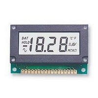
BEZEL, OEM22/24L
Manufacturer
ANDERS ELECTRONICS
Datasheet
1.MB11.pdf
(2 pages)
Specifications of MB11
Accessory Type
Bezel
External Length / Height
35mm
External Width
65mm
For Use With
OEM22/24L
Available stocks
Company
Part Number
Manufacturer
Quantity
Price

Part Number:
MB110
Manufacturer:
VISHAY/威世
Quantity:
20 000
Part Number:
MB110S-TP
Manufacturer:
MCC/美微科
Quantity:
20 000
Part Number:
MB110ST
Manufacturer:
ZV
Quantity:
20 000
Part Number:
MB111S043
Manufacturer:
FUJITSU/富士通
Quantity:
20 000
Company:
Part Number:
MB111S401
Manufacturer:
S
Quantity:
6 246
Company:
Part Number:
MB111T198PF-G-BND
Manufacturer:
FUJI
Quantity:
40
Part Number:
MB111T198PF-G-BND
Manufacturer:
FUJI/富士电机
Quantity:
20 000
Company:
Part Number:
MB112A102
Manufacturer:
FUJITSU
Quantity:
1 300
Company:
Part Number:
MB112S400
Manufacturer:
GENOA
Quantity:
6 227
Company:
Part Number:
MB112S401
Manufacturer:
FUJ
Quantity:
6 222


The OEM22/24L is designed for 9/5V supply. Incorrect
supply polarity will destroy the module immediately. It is
ready for general use when connected as in figure 1, for
9V supply. For 5V supply, the module must be calibrated
before use as follows. Connect as in figure 2, apply
100mV to the inputs, from a calibrated source and adjust
VR1 until the display reads 1000.
The input range is 0-200mV. Over-range is indicated by
blanking the three least significant digits and displaying a
"1" in the most significant digit.
For 9V operation it is recommended to power from a 9V
battery. The inputs are intended to float with respect to the
supply but if they do not float they must be no closer than
1.5V from either VDD or VSS (VDD-1.5V and VSS+1.5V).
See the circuits for non-floating inputs below.
The low BAT voltage can be set adjusting VR2 but it is not
recommended to operate with a supply voltage below 7V.
DC VOLTAGE MEASUREMENT
DC CURRENT MEASUREMENT
Revision 8 17/011/04
DC VOLTAGE OFFSET
NON FLOATING INPUTS (a)
USER INSTRUCTIONS
APPLICATION CIRCUITS
The input impedance becomes R1+R2. Choose accurate stable
resistors. Typically, R1=1MΩ. 9MΩ is a practical upper limit.
To measure voltages greater than 200mV
an attenuator is required.
EXAMPLES
10V 1500rpm
V
2V
V
IN
IN
anders
Where a single 5V supply is not
suitable but you must connect your
input signal ground to the module
supply ground, then either of these two
non-floating input circuits can be used.
Note that the module is set in the 9V
supply mode.
=V
Shunt resistance
It is important to note the power
dissipation in the shunt and choose
resistor rating accordingly
Tel: +44 (0)20 7380 8167 Fax: +44 (0)20 7874 1908 http://www.anders.co.uk
Display
1.999V
D
EXAMPLES
To achieve a zero display reading
for a non-zero voltage input,
apply the offset voltage between
COM and INLO.
For a positive offset apply a
Positive signal to INLO w.r.t.
COM.
Apply the input signal between
INHI and COM
P
x
S
R1+R2
Current
200mA
=
R2
2A
Vs
I
IN
electronics plc
2
199.9mV 1MΩ 110KΩ
150mV
= I
V
V
D
IN
D
0.1Ω
.
2
1Ω
R
max. is 199.99mV
R
R
S
S
S
1MΩ
R1
=
Ω
Vs
I
IN
0.04W
0.4W
P
Ω
15KΩ
S
R2
Bayham Place, London NW1 OEU UK
MULTI-RANGE DC CURRENT MEASUREMENT
NON FLOATING INPUTS (b)
All annunciators are connected to BP for suppression
purposes. To light up, cut the trace between the selected
annunciator pad and BP track and then link with solder
the annunciator pad to the XBP pad next to it.
For 5V operation, INLO must be connected to TST for
non-floating inputs (as fig. 2) and to the analogue common
pin COM for floating inputs. The low BAT annunciator
needs to be turned of by adjusting VR2.
MULTI-RANGE DC VOLTAGE MEASUREMENT
DC VOLTAGE RATIO MEASUREMENT
CONNECTION DIAGRAM
To determine the ratio between two
voltages apply the inputs as shown.
Displayed reading
Over range occurs when
Using the formulae choose resistors to
ensure the analogue inputs are no
closer than 1.5V from either VDD or
VSS (VDD-1.5V or VSS+1.5V)
BASIC CONFIGURATION
For multi-range, use a 2 pole,
5 way rotary switch. 1 pole for
range select and the other to
connect the appropriate
decimal point to XBP.
For multi-range, use a 2 pole,
4 way rotary switch. 1 pole for
range select and the other to
connect the appropriate
decimal point to XBP.
=
V2
V1
X 1000
V2
V1
>
2
Related parts for MB11
Image
Part Number
Description
Manufacturer
Datasheet
Request
R

Part Number:
Description:
SCALE, 78X60, PM, 0-100
Manufacturer:
ANDERS ELECTRONICS
Datasheet:
Part Number:
Description:
SCALE, 96X75, PM, 0-100
Manufacturer:
ANDERS ELECTRONICS
Datasheet:

Part Number:
Description:
DPM, LED, DIN, DC VOLTMETER
Manufacturer:
ANDERS ELECTRONICS
Datasheet:
Part Number:
Description:
DPM, LED, DIN, AC VOLTMETER
Manufacturer:
ANDERS ELECTRONICS
Datasheet:

Part Number:
Description:
DPM, LCD, 4-20MA, PROCESS
Manufacturer:
ANDERS ELECTRONICS
Datasheet:

Part Number:
Description:
DPM, LCD, THERMOMETER
Manufacturer:
ANDERS ELECTRONICS
Datasheet:

Part Number:
Description:
DPM, LCD
Manufacturer:
ANDERS ELECTRONICS
Datasheet:

Part Number:
Description:
DPM, LCD, 3.5DIGIT, MINI
Manufacturer:
ANDERS ELECTRONICS
Datasheet:

Part Number:
Description:
METER, 78X60, 0-1MA
Manufacturer:
ANDERS ELECTRONICS
Datasheet:
Part Number:
Description:
METER, 78X60, 0-100UA
Manufacturer:
ANDERS ELECTRONICS
Datasheet:
Part Number:
Description:
METER, 96X75, 0-1MA
Manufacturer:
ANDERS ELECTRONICS
Datasheet:

Part Number:
Description:
AMP METER
Manufacturer:
ANDERS ELECTRONICS
Datasheet:

Part Number:
Description:
METER, CIRCULAR, 0-200UA
Manufacturer:
ANDERS ELECTRONICS
Datasheet:

Part Number:
Description:
METER, CIRCULAR, 0-200UA
Manufacturer:
ANDERS ELECTRONICS
Datasheet:

Part Number:
Description:
METER, MOVING, COIL, 0-100UA
Manufacturer:
ANDERS ELECTRONICS
Datasheet: