EMV 1125 LASCAR, EMV 1125 Datasheet - Page 2
EMV 1125
Manufacturer Part Number
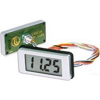
EMV 1125
Description
Voltage Meter
Manufacturer
LASCAR
Datasheet
1.EMV_1125.pdf
(2 pages)
Specifications of EMV 1125
No. Of Digits / Alpha
3-1/2
Meter Function
DC Voltmeter
Width
1.7"
Accuracy
+/- (0.05% Of Input +/- 1 Count)
Signal Input Type
200mV
Character Size
0.5"
Height
0.84"
Lead Free Status / RoHS Status
na


WIRE CONNECTIONS
0. Black (BK)
1. Brown (BR)
2. Red (RD)
3. Orange (OR) Vref
4. Yellow (YL)
5. Green (GR)
6. Blue (BL)
7. Violet (VI)
8. Grey (GY)
9. White (WT)
SCALING and CALIBRATION
A calibration circuit and two resistors (Ra and Rb) may be added on the
EMV 1125 or T/BLK-4 board (cut Link La if fitting Ra) to alter the full
scale reading of the meter - see table. Note that the meter will have to
be (re-)calibrated by adjusting the potentiometer.
Specifications liable to change without prior warning
Required F.S.R.
200mV
2V
20V
200 A
2mA
20mA
200mA
Adding an input filter and scaling resistors when T/BLK-4 is not used
Note: To reduce noise on the meter's input, fit the input filter components (1M
and 10nF) shown above. The input filter is fitted as standard on T/BLK-4.
APPLICATIONS
Do not connect more than one meter to the same power supply if the meters cannot use the same signal ground. Taking any input beyond the power supply rails
will damage the meter. Keep leads short to ensure noise-free operation.
Measuring a floating voltage
source of 200mV full scale.
Add Ra and Rb and cut Link La to
increase the measurement range.
Supply
Voltage
INPUT
+
-
V-
COM
V+
IN HI
IN LO
DP COM Common connection for decimal points DP1, DP2 and DP3, see below.
DP1
DP2
DP3
Input Voltage
Negative power supply connection.
The ground for the analogue section of the A/D converter, held actively at 2.8V (nom.) below V+.
COM must not be allowed to sink excessive current (>100 A) by connecting it directly to a higher voltage.
Positive power supply connection.
Connection for calibration circuit (see diagram below).
Positive measuring differential input.
Negative measuring differential input. (On T/BLK-4, IN LO is connected to COM via normally-closed Link L2.)
199.9
19.99
1.999
LASCAR ELECTRONICS LTD.
+200mV
910k
N/A
1M
Ra
0R
0R
0R
0R
(EMV 1125)
(or make appropriate solder link on T/BLK-4)
Connect to DP COM to display required decimal point.
100R
100k
N/A
10R
10k
Rb
1k
1R
(Yellow/4)
and SCREW TERMINAL FUNCTIONS
(Green/5)
IN LO
IN HI
Adjust
Adjust
Adjust
Adjust
Adjust
Ad
Adjust
EMV 1125
CAL
Measuring current.
Recalibrate the module.
The current to be measured must be
isolated from the module's power supply.
just
Supply
Voltage
IN HI and IN LO must be no closer than 1V to either the positive or negative supply.
Rb =
Issue 10
LASCAR ELECTRONICS INC.
0.2
I
Connecting to T/BLK-4
Adding a calibration circuit when T/BLK-4 is not used
Note: The calibration circuit must always
be fitted, even when scaling resistors are
not fitted. This circuit is fitted as standard
on T/BLK-4.
Current to be
measured
February/2006
(T.BLK-4)
IRCN 0539
LASCAR ELECTRONICS (HK) LIMITED
Supply
Voltage
Measuring a supply voltage.
(min. 7.5V, max. 15V)
Cut Links La and L2.
Recalibrate the module.
M.C.
R
Applies to EMV 1125/2
(Orange/3)
(Brown/1)
(Red/2)
COM
Vref
V+
Related parts for EMV 1125
Image
Part Number
Description
Manufacturer
Datasheet
Request
R

Part Number:
Description:
Voltage Meter
Manufacturer:
LASCAR
Datasheet:
Part Number:
Description:
Voltage Meter
Manufacturer:
LASCAR
Datasheet:

Part Number:
Description:
Voltage Meter
Manufacturer:
LASCAR
Datasheet:

Part Number:
Description:
Voltage Meter
Manufacturer:
LASCAR
Datasheet:


Part Number:
Description:
DPM, LED, 3.5DIGIT
Manufacturer:
LASCAR
Datasheet:

Part Number:
Description:
Voltage Meter
Manufacturer:
LASCAR
Datasheet:

Part Number:
Description:
Status Indicator
Manufacturer:
LASCAR
Datasheet:

Part Number:
Description:
Power Supply, Benchtop, 1.5 - 30Vdc (0-1 Amp)
Manufacturer:
Lascar Electronics
Datasheet: