FPSI 1010 LASCAR, FPSI 1010 Datasheet - Page 3
FPSI 1010
Manufacturer Part Number
FPSI 1010
Description
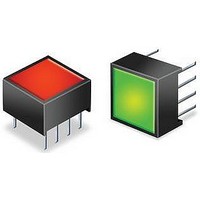
Status Indicator
Manufacturer
LASCAR
Datasheet
1.FPSI_1010.pdf
(4 pages)
Specifications of FPSI 1010
Panel Cutout Height
0.5"
Panel Cutout Width
0.5"
No. Of Pins
8
Length/height, External
10mm
Peak Reflow Compatible (260 C)
No
Accuracy
0.40%
External Width
10mm
Supply Voltage
5V
External Depth
6.2mm
Display Font Color
Red/Green
Leaded Process Compatible
No
Rohs Compliant
Yes
Lead Free Status / RoHS Status
Lead free / RoHS Compliant


FPSI 1010
Specifications liable to change without prior warning
PIN FUNCTIONS
1. V+
2. 0V
3. Vin
4. STORE Connecting to V-:
5. RED1
6. GREEN This pin goes High when the voltage on Pin 3 is between the switching thresholds V1 and V2.
7. RED2
8. Vref
CONFIGURING THE LEVEL INDICATOR
The indicator is factory configured with colour switching thresholds, as follows:
To change this setting, proceed as follows.
To facilitate programming of the colour switching thresholds, an optional programmer is available - FPSI 1010 PROG.
SCALING
The FPSI 1010 features a voltage measurement range of 2.5Vd.c. on Vin (Vref not connected).
Two resistors Ra and Rb may be used to alter the measurement range of the indicator.
Use the following formulae to calculate values of Ra and Rb for voltage and current measurement.
High
Ok
Low
High
Ok
Low
V1 = 1.67V and V2 = 3.33V (when Vref is connected to +5.0V)
V1 = 0.83V and V2 = 1.67V (when Vref is not connected)
Vref connected to 5.0V
GREEN
GREEN
RED2
RED1
RED2
RED1
Voltage Scaling
Ra = Rb (
Rb = 1k
Current Scaling
Ra = 0
Rb =
(S closed)
I
W
in(full scale)
Positive power supply to the level indicator.
Negative power supply to the level indicator.
Measuring input with reference to 0V.
This pin goes High when the voltage on Pin 3 is lower than the switching threshold V1.
This pin goes High when the voltage on Pin 3 is higher than the switching threshold V2.
This pin reflects the reference voltage for the module's measurement circuit.
Connect Vref to +5.0V to change the indicator's measurement range from 0 to 2.5V to 0 to 5.0V.
W
V2
V1
0V
V2
V1
0V
V+
V+
Vin
2.5
2.5V
- 1)
.
- Connect the V+ and 0V pins of
the FPSI 1010 to a 5Vd.c. supply.
- Apply the first desired voltage (V1) to Vin, then press S
- Module flashes Green to indicate that the V1 level has been stored.
- Disconnect the module. The module is now ready for use.
Step 1
Step 2
Step 4
Step 5
Step 3
- Apply the second desired voltage (V2) to Vin, then press S
- Module flashes Red to indicate that the V2 level has been stored.
- To enter solid LED mode, make sure Vin does not change, then press S
- To enter flashing LED mode, change Vin by 100mV or more, then press S
- Module flashes Red or Green to indicate that the LED mode has been stored.
Voltage Scaling
Ra = Rb (
Rb = 1k
Current Scaling
Ra = 0
Rb =
Vref not connected
(S open)
I
W
in(full scale)
W
See "Configuring The Level Indicator" for further details.
Vin
5.0
5.0V
www.lascarelectronics.com
- 1)
.
FPSI 1010
Vin or in
Issue 6
+5V
I
0V
power supply
4.75 to 5.5V
input voltage
0 to V+
November/2006
Ra
2 Colour Voltage Level Indicator
{
{
Rb
1
3
2
STORE
V+
Vin
0V
S
.
IRCN
STORE
M.C.
FPSI 1010
.
S
1
2
3
4
: 716 - Page 3 of 4
Applies to FPSI 1010/1
V+
0V
Vin
STORE
FPSI 1010
Vref
STORE
GREEN
8
STORE
RED2
RED1
.
Vref
.
8
7
6
5
Related parts for FPSI 1010
Image
Part Number
Description
Manufacturer
Datasheet
Request
R

Part Number:
Description:
Status Indicator
Manufacturer:
LASCAR
Datasheet:

Part Number:
Description:
Device Programmer
Manufacturer:
LASCAR
Datasheet:

Part Number:
Description:
Voltage Meter
Manufacturer:
LASCAR
Datasheet:


Part Number:
Description:
DPM, LED, 3.5DIGIT
Manufacturer:
LASCAR
Datasheet:

Part Number:
Description:
Voltage Meter
Manufacturer:
LASCAR
Datasheet:

Part Number:
Description:
DPM, LCD, 3.5DIGIT, NEGATIVE RAIL
Manufacturer:
LASCAR
Datasheet:

Part Number:
Description:
Status Indicator
Manufacturer:
LASCAR
Datasheet:

Part Number:
Description:
Power Supply, Benchtop, 1.5 - 30Vdc (0-1 Amp)
Manufacturer:
Lascar Electronics
Datasheet: