PAXD0000 Red Lion Controls, PAXD0000 Datasheet - Page 13
PAXD0000
Manufacturer Part Number
PAXD0000
Description
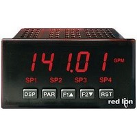
Multifunction Meter
Manufacturer
Red Lion Controls
Type
Ammeter/Voltager
Datasheet
1.PAXD0000.pdf
(28 pages)
Specifications of PAXD0000
No. Of Digits / Alpha
5
Meter Range
± 200uA To ± 2A / ± 200mV To ± 300V / 100ohm To 10kohm
Digit Height
14.2mm
Power Consumption
15VA
Operating Temperature Range
0°C To +50°C
Supply Voltage Ac, Min
85V
Brand/series
PAX
Connection Type
Cage-Clamp
Cut Out, Panel
1⁄8 DIN
Dimensions
4.2" L × 3.8" W × 1.95" H
Display Digit Height
0.56 "
Display Resolution
10 nA to 0.1 mA/10 μV to 10 mV
Display Type
LED
Function
Ammeter/Voltage
Meter Type
Panel
Number Of Digits
6
Primary Type
Electronic
Range, Measurement
±200 μADC to ±2 ADC/±200 mVDC to ±300 VDC
Special Features
Programmable Function Keys
Standards
CE Marked, cUL Recognized
Termination
Cage Clamp
Voltage, Input
85 to 250 VAC
Voltage, Supply
85 to 250 VAC
Character Size
0.56"
Rohs Compliant
Yes
Lead Free Status / RoHS Status
Lead free / RoHS Compliant


3.3 USER INPUT WIRING
Inputs, then skip this section. Only the appropriate User Input terminal has to be wired.
Sinking Logic
Terminal 8-10:
Terminal 7:
Sinking Logic
Terminals 9-11
Terminal 8
3.4 SETPOINT (ALARMS) WIRING
3.5 SERIAL COMMUNICATION WIRING
3.6 ANALOG OUTPUT WIRING
4.0 R
PAXH ONLY
Before connecting the wires, the User Input Logic Jumper should be verified for proper position. If not using User
In this logic, the user inputs of the
meter are internally pulled up to +5 V
with 22 K resistance. The input is active
when it is pulled low (<0 .9 V).
In this logic, the user inputs of the
meter are internally pulled up to +5 V
with 22 K resistance. The input is
active when it is pulled low (<0 .9 V).
}
}
* Display Readout Legends may be locked out in Factory Settings.
** Factory setting for the F1, F2, and RST keys is NO mode.
Connect external
switching device between
appropriate User Input
terminal and User Comm.
KEY
DSP
PAR
F1
F2
RST
Connect external switching device between
appropriate User Input terminal and User Comm.
EVIEWING THE
"
!
DISPLAY MODE OPERATION
Index display through max/min/total/input readouts
Access parameter list
Function key 1; hold for 3 seconds for Second Function 1**
Function key 2; hold for 3 seconds for Second Function 2**
Reset (Function key)**
F
RONT
See appropriate plug-in card bulletin for details.
Sourcing Logic
Terminal 8-10: + VDC thru external switching device
Terminal 7: -VDC thru external switching device
13
Sourcing Logic
Terminals 9-11:
Terminal 8:
In this logic, the user inputs of the meter are
internally pulled down to 0 V with 22 K
resistance. The input is active when a voltage
greater than 3.6 VDC is applied.
+ VDC through external switching device
-VDC through external switching device
In this logic, the user inputs of the meter are
internally pulled down with 22 K resistance.
The input is active when a voltage greater
than 3.6 VDC is applied.
PROGRAMMING MODE OPERATION
Quit programming and return to display mode
Store selected parameter and index to next parameter
Increment selected parameter value
Decrement selected parameter value
Hold with F1
B
UTTONS AND
"
, F2
!
to scroll value by x1000
D
ISPLAY
Related parts for PAXD0000
Image
Part Number
Description
Manufacturer
Datasheet
Request
R

Part Number:
Description:
Counter
Manufacturer:
Red Lion Controls
Datasheet:
Part Number:
Description:
Miniature Length Sensor
Manufacturer:
Red Lion Controls
Datasheet:
Part Number:
Description:
Model Lsc - Single Channel Output Length Sensor
Manufacturer:
Red Lion Controls
Datasheet: