ACM20-5-AC1-R-F-C Murata, ACM20-5-AC1-R-F-C Datasheet - Page 3
ACM20-5-AC1-R-F-C
Manufacturer Part Number
ACM20-5-AC1-R-F-C
Description
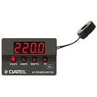
Power Meter
Manufacturer
Murata
Datasheet
1.ACM20-5-AC1-R-C.pdf
(6 pages)
Specifications of ACM20-5-AC1-R-F-C
No. Of Digits / Alpha
4
Meter Range
85V To 264V / 0A To 32A / 0W To 9999W / 47Hz To 63Hz
Digit Height
9.14mm
Power Consumption
250mW
Operating Temperature Range
0°C To +60°C
Supply Voltage Max
264VAC
Lead Free Status / RoHS Status
Lead free / RoHS Compliant


3. Calibration: Due their digital design, ACM20 power meters cannot be
4. Wiring: All power supply wiring must be rated for the voltages and
5. Supply Fusing, and Grounding: Wires specifi ed in the Functional
TYPICAL WIRING DIAGRAMS
Note: If the ACM20 displays zero Watts with
power applied to the load, reverse the direction
of the wire passing through the CT's center hole.
See Technical Note 6 for more information.
When the continuous auto-cycling mode is initially selected, the unit
will briefl y display ‘Auto On’ before continuous cycling begins. Mo-
mentarily touching the ‘SEL’ button again will cause the unit to briefl y
display ‘Auto OFF’ before it returns to the fi xed VOLTS reading mode.
calibrated in the fi eld. ACM20 power meters are factory-calibrated to
meet their specifi ed accuracies with the supplied L1 current trans-
former. Use of any other current transformer will produce signifi cant
errors for the Amps, Watts, and Power Factor measurements.
Contact Murata Power Solutions if additional information is required
regarding calibration, setup, or any other technical issue pertaining to
ACM20 power meters.
currents they will carry and must comply with any code or applica-
tion-mandated requirements pertaining to the user’s specifi c installa-
tion.
Specifi cations section must be used for making connections to
ACM20 series power meters. No connection is required for earth/
chassis ground.
ACM20 series power meters are not internally fused. Terminal block
TB1 is to be used only for powering the power meter's internal circuitry;
it must not be used to supply power to external loads. The supply wires
feeding these power meters must be fused with a 0.5A/250V time
delay/time lag fuse, in accordance with applicable regulatory codes.
Epoxy encapsulation
Polarity dot on bottom
Figure 1. Wiring diagram for 110/120V single phase systems
www.murata-ps.com/dpm
H
120 Vac (50/60 Hz)
6. Current Transformer Polarity: In order to perform accurate Watts
7. Connector Torque Ratings: It is important to tighten TB1’s, screw-
8. Isolation: Except for the 2-56 thread metallic mounting studs, all of
Fuse*
LOAD
120 V
Wire insulation must be stripped to within ±10% of the stated dimen-
sions, and wires should be inserted into TB1 such that their insulation
is not pinched by the screw terminal.
and Power Factor measurements, connections to the two rear power
supply inputs, TB1-A and TB1-B, and built-in current transformer L1
must have the proper polarity. That is, the load current fl owing in the
wire passing through L1's center hole must have the same polarity as
the line voltage connected to TB1-A and TB1-B.
The wiring diagrams in Figures 1-4 ensure that, for a purely resistive
load, current fl owing in current transformer L1’s primary circuit will
have the same polarity as the applied voltage at TB1. If proper polarity
is not followed, the Watts and Power Factor readings will be zero. To
correct a zero Watts reading, simply reverse the direction of the load
wire passing through the hole in L1.
terminals to their rated torque specifi cation of 3.6 pound-inches
(0.4Nm). Proper tightening will minimize connector losses and ensure
safe, reliable operation.
the ACM20 power meter’s internal components (printed circuit board,
resistor, capacitors, current transformer L1’s secondary leads, etc.)
are at the ac-mains potential connected to TB1. ACM20 power meters
are designed to measure and be powered from one ac power-source
only. Any other connection schemes will introduce signifi cant mea-
surement errors.
N
03 Mar 2011 MPM_ACM20 Series.A09 Page 3 of 6
Four-Function AC Power Meters
ACM20 Series
email: sales@murata-ps.com
*See technical note 5.
B B
A A A
TB1
Related parts for ACM20-5-AC1-R-F-C
Image
Part Number
Description
Manufacturer
Datasheet
Request
R

Part Number:
Description:
Power Meter
Manufacturer:
Murata
Datasheet:

Part Number:
Description:
Murata Microblower 20x20 DCDC Driver Board - Samples Only
Manufacturer:
Murata
Part Number:
Description:
357-036-542-201 CARDEDGE 36POS DL .156 BLK LOPRO
Manufacturer:
Murata
Datasheet:
Part Number:
Description:
Manufacturer:
Murata
Datasheet:
Part Number:
Description:
Manufacturer:
Murata
Datasheet:
Part Number:
Description:
Manufacturer:
Murata
Datasheet:
Part Number:
Description:
Manufacturer:
Murata
Datasheet:
Part Number:
Description:
Manufacturer:
Murata
Datasheet:
Part Number:
Description:
Manufacturer:
Murata
Datasheet:
Part Number:
Description:
Manufacturer:
Murata
Datasheet:
Part Number:
Description:
BLM21BD751SN1On-Board Type (DC) EMI Suppression Filters
Manufacturer:
Murata
Datasheet:
Part Number:
Description:
BLM15AG100SN1On-Board Type (DC) EMI Suppression Filters
Manufacturer:
Murata
Datasheet:
Part Number:
Description:
NFE31PT222Z1E9On-Board Type (DC) EMI Suppression Filters
Manufacturer:
Murata
Datasheet:
Part Number:
Description:
Chip Coil
Manufacturer:
Murata
Datasheet: